15
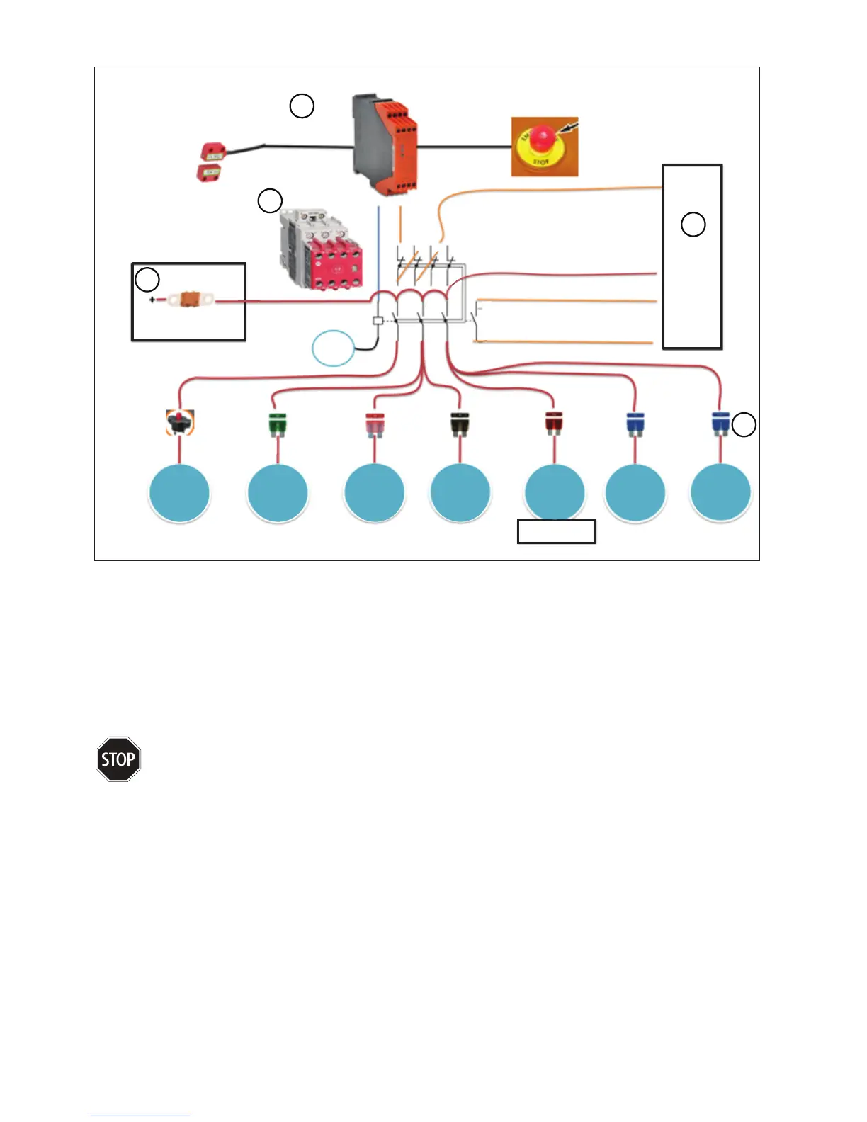
14. Safety Circuit Wiring
1
2
4
5
3
70A
BATTERY FUSE
BATTERY BOX
SAFETY
CONTACTOR
FRONT COVER
MAGNETIC INTERLOCK
SAFETY
RELAY
EMERGENCY
STOP BUTTON
MAIN
CONTROLLER
24V
GND
CONTACTOR
STATE
Safety Relay
- 24V
MIRROR
CONTACTS
41
31
2111
12 22 32
42
K1
A1
A2
1 3 5
3
2 4 6
4
F6
R50955
Fuse - Blade -
30A - 32V
Bussmann ATC-30
F5
1300573
Fuse - Blade -
4A - 32V
Bussmann
BK/ATC-4
F2
1300589
Fuse - Blade -
1A - 32V
Bussmann
ATC-1
F1
1300633
Fuse - Blade -
7.5A - 32V
Bussmann
BK/ATC-7 1/2
F1
1300614
Fuse - Blade -
15A - 32V
Bussmann
BK/ATC-15
F1
1300614
Fuse - Blade -
15A - 32V
Bussmann
BK/ATC-15
CB1
2300129
Circuit Breaker -
Resettable - 40A
Klixon 7851-13-
40i
LINEAR MOTORS
AND SOLENOID
BRUSH
MOTORS
VACUUM
MOTORS
RECYCLE
PUMP
UV
LIGHT
I/O
BOARD
DRIVE
MOTOR
(L)
DRIVE
MOTOR
(R)
Figure: 27
1 A safety contactor is used to safely remove power from all motors and the UV sterilizer system
2 The safety contactor is controlled by a safety relay. The safety relay will open the safety contactor when
either the Emergency Stop Button is pressed or the front cover is opened.
3 The system main controller monitors the status of the safety contactor to alert the operator when the circuit
is tripped.
4 A main battery fuse is provided in the battery box to protect the primary power wiring.
5 Branch fuses are provided to protect the branch wiring to each of the motors and subsystems.
Important:
The components of the safety circuit are essential to the safe operation of the machine. Never tamper
with or substitute any safety component, serious damage or injury may result.