20
downs of the line and false contacts;
- do not re-use old pre-existing cables;
- In case of long sections of cables (> 20 m) for N.O./N.C. controls (e.g. OPEN / CLOSE, STOP, PEDE-
STRIAN, etc.), in order to avoid gate malfunctions, it will be necessary to uncouple the various
controls using RELAYS or using our 750T-RELE device.
2. INTRODUCTION
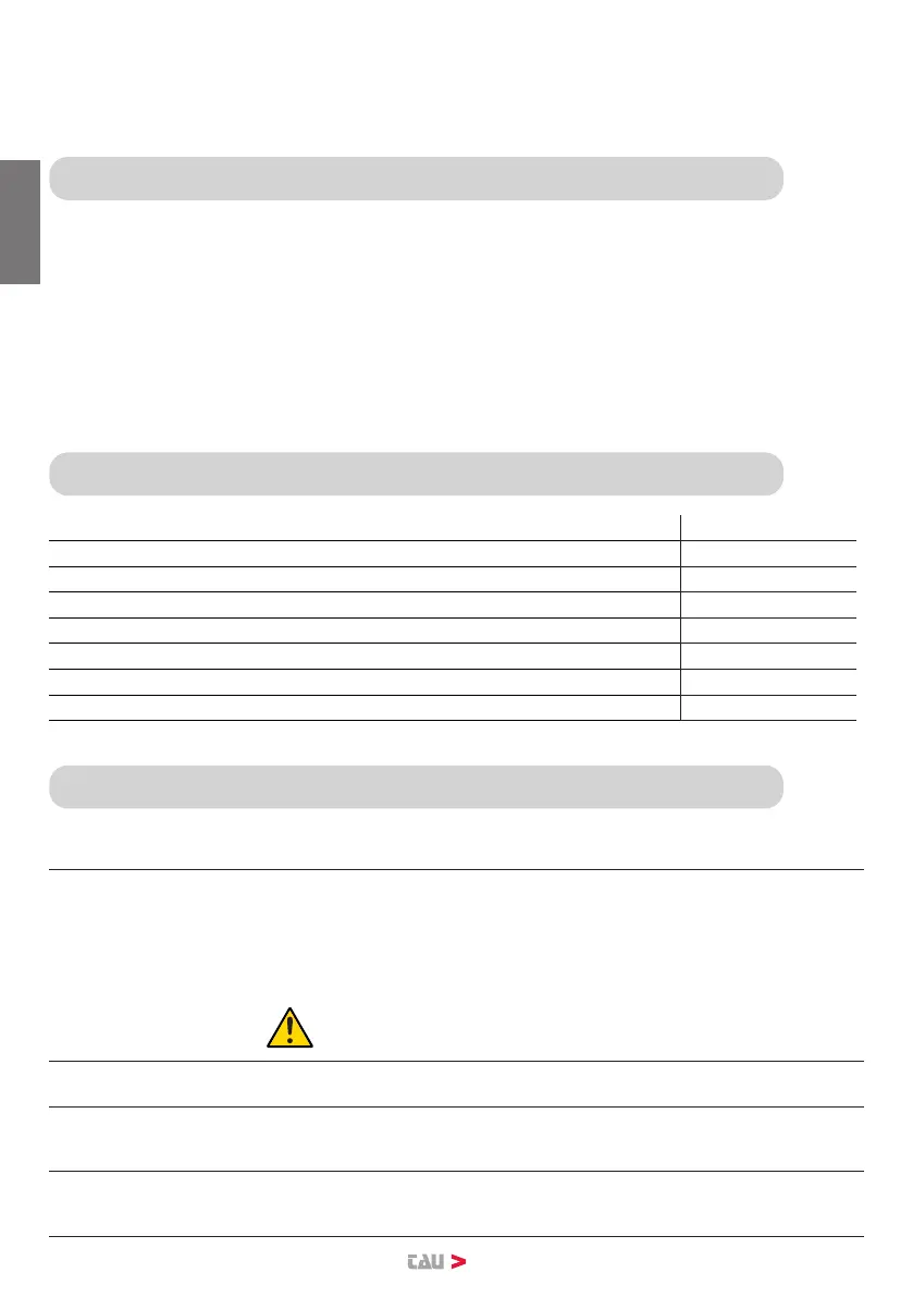
The K130MA board has two working modes, selectable through the J6 jumper (see wiring diagram).
J6 Not jumped: standard mode, i.e. the control unit is powered all the time;
J6 Jumped: low consumption mode, at the end of each maneuver the board automatically switches
OFF itself and all the auxiliary devices connected. The board will automatically switch
ON again activating the OP/CL contact or pressing the remote (mode where power is
supplied by other energy sources, ex. batteries charged by a photovoltaic panel). In
this way, the DL1 and DL2 LEDs ash every 4 seconds.
Once the connection is achieved, in low-energy mode, press the PROG button briey:
• All the green LEDs must be on (each of them corresponds to a Normally Closed input). The go o
only when the controls to which they are associated are operated.
• All the red LEDs must be o (each of them corresponds to a Normally Open input). The light up
only when the controls to which they are associated are operated.
3. TECHNICAL CHARACTERISTICS
Board power supply 13,5/18 V AC - 50 Hz
Max. absorption DC motor 250 W - 18 V DC
Fast acting fuse for protection of input power supply 13,5V AC (F4 - 5x20) F 16A
Fast acting fuse for protection of auxiliary circuits 18V DC (F3 - 5x20) F 3.15A
Motor power supply circuits voltage 18 V DC*
Auxiliary device circuits supply voltage 18 V DC*
Logic circuits supply voltages 5V DC
Operating temperature -20 °C ÷ +55 °C
1
18V DC for MASTER18QR and T-ONE10B
2
24VDC for MASTER-R and T-ONE8BR
4. CONNECTIONS TO TERMINAL BOARD
Termi-
nals
Function Description
FS1 - FS2 POWER SUPPLY
- 13,5V AC control unit power supply input (18V DC for MASTER18QR and
T-ONE10B).
- 18V AC control unit power supply input (24VDC for MASTER-R and T-O-
NE8BR)
Fed by the toroidal transformer and protected by the fuses (F 6,3A) on the
230V AC power supply.
For low power connection:
First connect the power supply given by the transformer and
then by the battery (terminals 1-2)
1 - 2
EXTERNAL
POWER
External power input (ex. Photovoltaic system 12V DC or battery 12V DC).
Notice: battery charger board not integrated.
3 - 6 PEDESTRIAN
N.O. input for PEDESTRIAN button - Controls prtial opening and closing (1/3
of the complete journey) and it is subject to the setting of DIP SW 2 and 4.
(3= PED - 6= COM)
4 - 6 OPEN/CLOSE
OPEN/CLOSE button N.O. input – Controls the opening and closing of the
automation and is regulated based on the function of dip-switches 2 and
4. (4= O/C - 6= COM)
ENGLISH