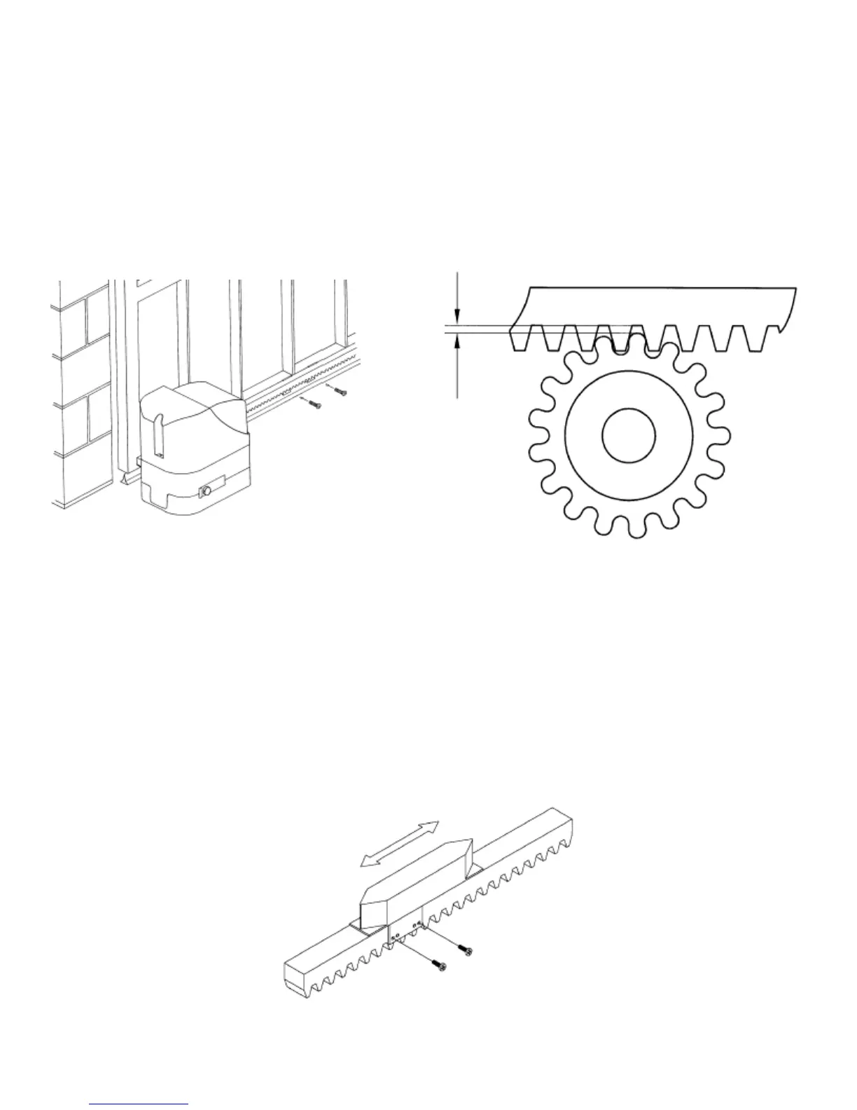
Tighten the screws (as shown in fig G) on both sides of the geared motor. Carry all cables across the holes obtained from the base of
the foundation counter plate.
Apretar los tornillos (tal como se indica en la fig.G1 - G2 ) en ambos lados del motorreductor. Pasar todos los cables a través de los
agujeros existentes en la base de la contraplaca de cimentación.
FIXING THE RACK
FIJACIÓN DE LA CREMALLERA
1 – 2 mm
Fig. H
Fig. I
Once the gate has been drilled, fix the rack to it using 6.3 mm. self-threading screws.
Después de haber perforado la hoja, fijar la cremallera a la verja con tornillos con autorroscado que tengan un diámetro de 6.3 mm.
FIXING AND ADJUSTING THE END LIMIT SLIDING BLOCKS
(SPEED 5 - 8)
FIJACIÓN Y REGULACIÓN DE LOS PATINES DE FIN DE CARRERA
(SPEED 5 - 8)