After Sales Support TEL: 1300 922 271 EMAIL: service.australia@einhell.com
11
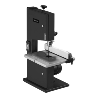
6. Technical data
Voltage: _______________________________ 230 V ~ 50Hz
Power:
_____________________ S1 180 W S2 15 min 250 W
Ideal speed no: ___________________________ 1400 min
-1
Blade length: ______________________________ 1400 mm
Max blade width: _____________________________ 8 mm
Blade speed: _____________________________900 m/min
Cutting height: __________________________80 mm / 90˚
__________________________________45 mm / 45˚
Throat: ____________________________________ 200 mm
Table size: ____________________________ 300 x 300 mm
Tilting range table: __________________________0˚ to 45˚
Workpiece size: ________________________ 400 x 400 mm
Weight: ____________________________________13.2 kg
Noise emission values
Sound and vibration values were measured inaccordance
with EN 61029.
C
utting
L
pA
sound pressure level 82.3 dB(A)
K
pA
uncertainty 3dB
L
WA
sound power level 92.8 dB(A)
K
WA
uncertainty 3dB
Load factor:
A load factor of S2 15 min (intermittent periodic duty) means
that you may operate the motor continuously at its nominal
power level (250 W) for no longer than the time stipulated
on the specications label (15minutes ON period). If you fail
to observe this time limit the motor will overheat. During
the OFF period the motor will cool again to its starting
temperature.
Wear ear-mus.
The impact of noise can cause damage to hearing.
Keep the noise emissions and vibrations to a minimum.
• Only use appliances which are in perfect working order.
• Service and clean the appliance regularly.
• Adapt
yourworkingstyletosuittheappliance.
• Donotoverloadtheappliance.
•
Ha
vetheapplianceservicedwhenevernecessary.
• Switchtheapplianceowhenitisnotinuse.
Residual risks
Even if you use this electric power tool in accordance with
instructions, certain residual risks cannot be ruled out.
The following hazards may arise in connection with the
equipment’s construction and layout:
1.
L
ung damage if no suitable protective dust mask is used.
2.
Damage t
o hearing if no suitable ear protection isused.
7. Before putting the machine
into operation
• Makesurethemachinestandssecurely,i.e.boltittoa
w
orkbench or solid base. There are two holes for this
purpose in the machine foot.
• Thesawtablemustbemountedcorrectly.
• A
llcoversandsafetydeviceshavetobeproperlytted
before the machine is switched on.
• Itmustbepossibleforthebladetorunfreely.
• Whenworkingwithwoodthathasbeenprocessedbefore,
w
atch out for foreign bodies such as nails or screws etc.
• BeforeyouactuatetheOn/Oswitch,makesurethat
the saw blade is correctly tted and that the machine’s
moving parts run smoothly.
• Beforeyouconnectthemachinetothepowersupply,
make sur
e the data on the rating plate is the same as that
for your mains.
8. Assembly
Caution! Pull out the power plug before carrying out any
maintenance, resetting or assembly work on the bandsaw!
8.1. Mounting the saw table (Fig. 1 - 5)
• Removethewebpanel(4).
• Placethesawtable(15)onthemachinehousing(25)from
the r
ight and fasten with 3 xing screws (27). Make sure
that the blade (26) is positioned exactly in the center of
the saw table.
• Re-insertthewebpanel(4).
• Inserttheplastictableinsert(17)intothetablefrom
abo
ve. Do this in such a way that a through-going slot is
the result.
• Todismantlethesawtable,proceedinreverseorder.
8.2. Tensioning the blade (Fig. 1/6)
•
C
AUTION!Remove the tension from the blade if the
bandsaw is not going to be used for some time. Be sure to
re-tension the blade before you start the machine.
•
T
urnthetighteningscrew(9)fortensioningtheblade(26)
in a clock
wise direction. The correct blade tension can
be checked by applying pressure to the side of the blade
with your nger, somewhere in the middle between the
two blade pulleys (7 + 8). You should only beable to bend
the blade (26) very slightly (approx.1-2 mm).
• IMPORTANT! The blade may break if the tension is too
high. BEWARE OF INJURY! If the tension is too low, the
powered blade pulley (7) will spin while the blade does
not move.
8.3 Adjusting the blade (Fig. 1/2)
•
C
AUTION!The blade tension has to be set correctly
before you can adjust the blade.
• Undo
thefasteners(13)andopenthesidecover(12).
 Loading...