After Sales Support TEL: 1300 922 271 EMAIL: service.australia@einhell.com
13
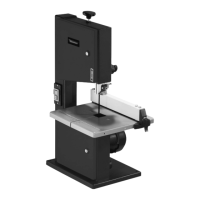
8.7. Blade selection
The blade supplied with the bandsaw is designed for all-
purpose use. When you select a blade you should have regard
to the following criteria:
•
U
seanarrowbladetocuttighterradiusthanyoucanwith
a wider blade
.
•
W
idebladesareusedtosawstraightcuts.
T
hisis
particularly important in cutting wood because the blade
has a tendency to follow the grain of the wood and there
by deviate easily from the cutting line.
•
F
inelytoothedbladesprovidesmoothercutsbutare
slo
wer than coarse blades.
Important: Never use warped or lacerated blades!
8.8. Changing the blade (Fig.14)
• M
ovethebladeguide(Fig.1/Item11)intoaposition
appr
oximately half way between the saw table
(Fig.1/Item 15) and the machine housing (Fig.2/Item 25).
• Undo
thefasteners(Fig.1/Item13)andopentheside
c
over (Fig. 1/Item 12).
• Removethewebpanel(Fig.3/Item4).
•
T
urnthetighteningscrew(Fig.1/Item9)anti-clockwiseto
r
emove the tension from the blade (Fig.2/Item 26).
•
R
emovetheblade(Fig.2/Item26)fromthebladepulleys
(F
ig.1/Item 7 & 8) and take out through the slot in the table
(Fig.1/Item 15).
•
F
itthenewblade(Fig.2/Item26),alignedcentrallyonthe
b
lade pulleys (Fig.1/Item 7 & 8).
•
T
heteethoftheblade(Fig.2/Item26)mustpoint
downwards in the direction of the table.
• Tension
theblade(Fig.2/Item26)(see8.2)
• Close
thesidecover(Fig.1/Item12)again.
• Mount
thewebpanel(Fig.3/Item4)again.
8.9. Changing the rubber tires on the blade pulleys
After a certain time the rubber tires (Fig.15/Item 3) on the
blade pulleys (Fig.1/Item 7 & 8) will get worn by the sharp teeth
of the blades and must be replaced.
• Openthesidecover(Fig.1/Item12).
• Remove
theblade(Fig.2/Item26)(see8.7).
•
Lifttheedgeofthetire(Fig.15/Item3)withasmall
screwdriver (Fig.15/Item f) and remove from the upper
blade pulley (Fig.1/Item 8).
• Repeat
forthelowerbladepulley(Fig.1/Item7).
•
Fitthenewtire(Fig.15/Item3),replacetheblade
(Fig.2/Item 26) and close the side cover (Fig.1/Item12).
8.10. Changing the table insert (Fig.16)
To prevent increased likelihood of injury the table insert
(Fig.16/Item 17) should be changed whenever it is worn
or damaged.
• Detach
thetable(Fig.1/Item15)(see8.1).
• Lift
outtheworntableinsert(Fig.16/Item17).
• Fitthereplacementtableinsertbyfollowingtheabove
in reverse.
8.11. Extractor sockets
The bandsaw is equipped with extractor sockets (Fig.1/Item 6)
for extracting sawdust and chips.
9. Control elements
9.1. On/O switch (Fig.17)
• Toturnthemachineon,pressthegreenbutton“l”(g).
• Toturnthemachineoagain,presstheredbutton
“0“
(h).
•
Y
ourbandsawhasaswitchwithundervoltagerelease.
After a power failure you must re-activate the switch.
9.2. Parallel stop (Fig.18)
• Pushtheclip(21)ontheparallelstop(24)upwards.
•
M
ovetheparallelstop(24)alongthetable(15),from
either the r
ight or left of the blade (26), and position
as required.
•
P
ushtheclip(21)downtoxtheparallelstop(24).Ifthe
clip (21) does not g
ive enough hold, turn it clockwise
several times until the parallel stop is securely xed.
•
Y
oumustalwaysensurethattheparallelstop(24)is
positioned parallel to the blade (26).
10. Operation
Caution! After every new adjustment we recommend to make
a trial cut in order to check the new settings.
•
F
orallcuttingoperationsitisimportanttopositiontheblade
guide (Fig.1/Item 11) as close as possible to the workpiece
(see 8.5).
•
A
lwaysguidetheworkpiecewithbothhands,holding
it at on the table (Fig.1/Item 15) in order to prevent the
blade (Fig.2/Item 26) from jamming.
•
F
eedtheworkpieceatauniformspeedthatenablesthe
blade t
o cut through the material without diculty and
without blocking.
•
A
lwaysusetheparallelstop(Fig.2/Item
2
6)
on
allcutsfor
which they ar
e intended.
•
A
lwaysaimatmakingacompletecutinonepassrather
than in a st
op-and-go operation requiring the workpiece
to be withdrawn. If you have to withdraw the workpiece,
switch o the bandsaw rst and wait for the blade (Fig.2/
Item 26) to stop before freeing the workpiece.
•
T
heworkpiecemustalwaysbeguidedbythelongerside
dur
ing cutting.
Important! When handling narrower workpieces, it is
essential to use a push stick.The push stick (Fig.20/Item 28)
must always be kept close at hand at the hook (Fig.20/Item 29)
provided for that purpose on the side of the saw.
 Loading...