EasyManua.ls Logo

Taxitronic TX52 - Electrical Installation

Taxitronic TX52
16 pages
Print Icon
To Next Page IconTo Next Page
To Previous Page IconTo Previous Page
Loading...
INTERFACOM, S.A.
Inst TX52_TX40_007_en.doc 5
2. ELECTRICAL INSTALLATION
To access the connectors it is necessary to open the Connector cover
- Take out the screw that seals the cover
- On TX52, liberate a clip on the bottom of the taximeter
The taximeter has the following connectors:
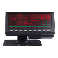
(1) Power Supply
Contact number
Color
Function
X = Required
1, 2
Black
Ground
X
3, 4
Red
Battery 12V
X
5
Yellow
Position lights
6
Blue
Contact Key
X
7
Green
Rooflight
8
Violet
Passenger sensor
9
Green / White
Distance pulses
X
10
Brown
External signal
(2) Impulse Generator
Contact number
Color
Function
1
Mesh
Ground
2
Red
5V output
3
Green
Signal
4
Blue
Complemented signal
(3) Parallel Rooflight
Contact number
Color
Function
1
Light 6
2
Light 5
3
Light 4
4
Light 3
5
Light 2
6
Light 1 (Free)
7
Position lights output
8
Ground

Related product manuals