1-6
TO THE INSTALLER
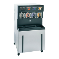
Models 345, 346, 349, 355 NPR
To the Installer
1
9. Set the secondary regulator on the CO
2
tank to
50 psi (3.45 bar) for the syrup tanks or the BIB
pumps.
Figure 1-6
10. Turn the cold water supply on.
11. Check for CO
2
leaks. Close the valve on the top of
the CO
2
tank. Watch the high-pressure gauge. It
should hold pressure. If it does not, there is a CO
2
leak. Use a soap solution to locate and repair the
leak.
Important! Ensure that the Bag-in-Box switch is
enabled.
12. The CO
2
regulator assembly (primary regulator)
inside the freezer should be set at 40 to 45 psi (2.76
to 3.10 bar).
13. The CO
2
low-pressure switch requires at least 21 psi
(1.45 bar) before the freezer will start. It is set to cut
out at 7 psi (0.483 bar) and cut in at 21 psi (1.45 bar).
14. There are check valves in the CO
2
, syrup, and water
lines to prevent any backflow of soda water, product,
or CO
2
.
Remote Condenser Assembly Units
Preparation
Uncrate the condenser assemblies. After inspecting them
for damage, position them in the desired location. Two
remote condenser assemblies are required for each
freezer (one condenser per compressor).
Remote condensers require a minimum of 6 in. (152 mm)
air space on the rear and both sides. This is necessary
for adequate air flow. Failure to follow this instruction may
cause poor freezer performance and damage the
equipment.
Refrigeration Charging and Line
Construction
Each condenser assembly is shipped with a refrigerant
holding charge sufficient to prevent moisture
contamination 8 oz. (227 g) HP62. This holding charge
will become part of the total system charge.
The condenser assemblies are shipped with the total
amount of refrigerant required for a typical installation of
50 ft. (15 m). For other installation configurations, use the
following chart for line sizing and for adding required
refrigerant.
Recommended System Refrigerant Charge
Table 1-1
Note: Maximum line length is 100 ft. (30 m) To meet
individual installation requirements, the lines must be
purchased and constructed locally.
Line Size
Liquid Line—Requires 3/8 in. refrigerant grade copper
tubing (hard or soft).
Note: Insulating the liquid line is recommended if it is
exposed to high ambient conditions. This will reduce heat
accumulation and prevent the formation of flash gas in
the liquid line.
Discharge Line—Requires 1/2 in. refrigerant grade
copper tubing (hard or soft).
Discharge/Liquid Line
Length
Required Charge
Up to 50 ft. (15 m) line sets
200 oz. / 567 kg
50 to 75 ft. (15 to 23 m)
214 oz. / 607 kg
(add 14 oz. / 40 kg)
75 to 100 ft. (23 to 30 m)
228 oz. / 646 kg
(add 28 oz. / 79 kg)