22-1322-13TX / TXH / TXB 180S - 400L (Rev. 4/23/07)TX / TXH / TXB 180S - 400L (Rev. 4/23/07)
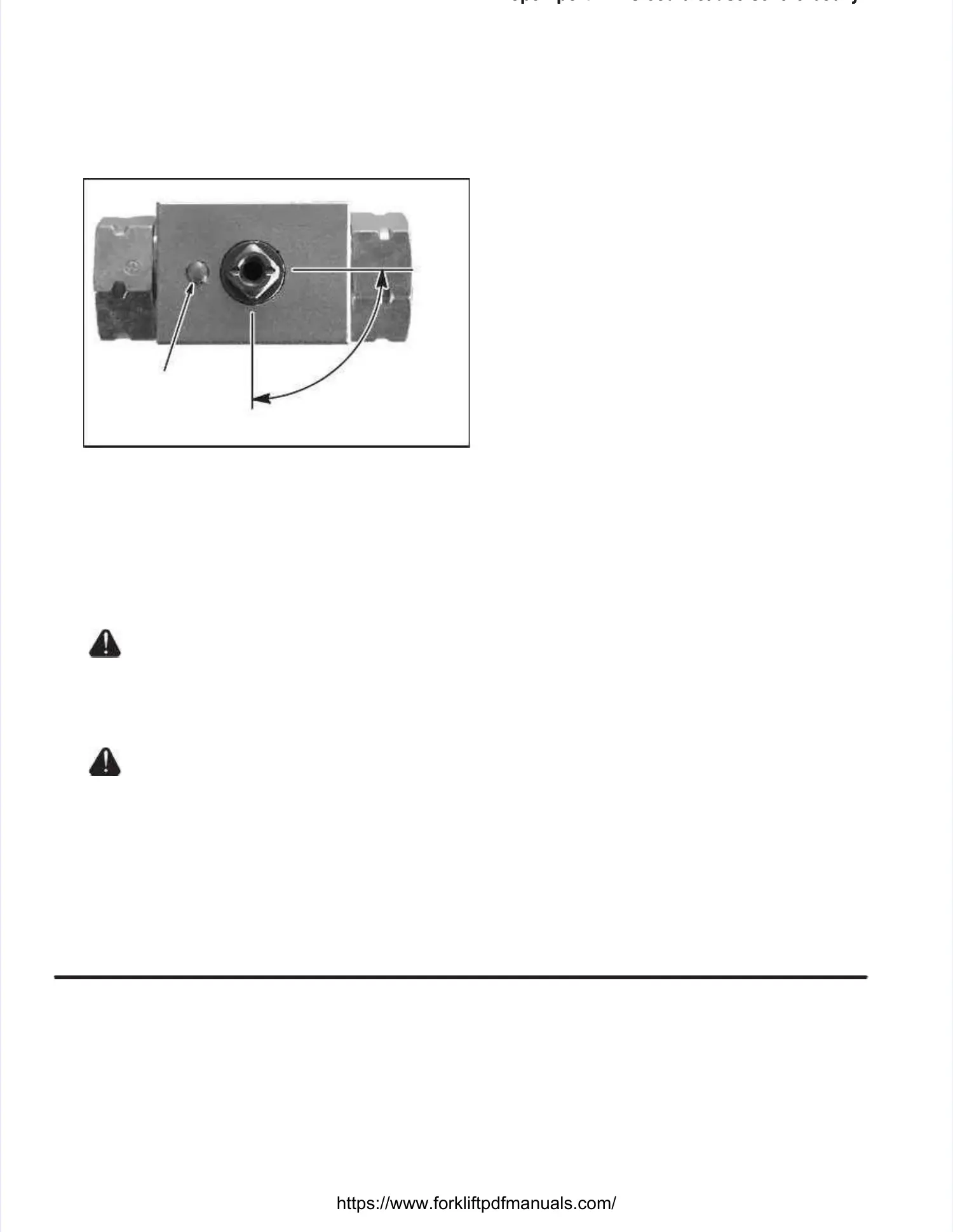
point toward the sides of the valve block (notepoint toward the sides of the valve block (note
position of valve stem in Illustration 22-19).position of valve stem in Illustration 22-19).
2.2. InsInstaltall the lol the lock plck plate oate over tver the valhe valve stve stem.em.
Ensure that the notch of the lock plate is secu-Ensure that the notch of the lock plate is secu-
red by the stud on the valve block (see Illustra-red by the stud on the valve block (see Illustra-
tion 22-19).tion 22-19).
3.3. InsInstaltall cl collollar oar over ver valvalve ve stestem.m.
4.4. InsInstaltall sl stem tem scrscrew aew and tnd tighightenten..
FULLYFULLY
OPENOPEN
1/4 turn1/4 turn
FULLY CLOSEDFULLY CLOSED
STUDSTUD
Illustration Illustration 22-19. 22-19. Closing and Closing and Opening TheOpening The
Lowering Lowering ValvValvee
Setting Hydraulic PressuresSetting Hydraulic Pressures
Hydraulic pressures must be set at recommendedHydraulic pressures must be set at recommended
engine speed. engine speed. The hydraulic The hydraulic fluid should fluid should be atbe at
operating temperature before adjusting hydraulicoperating temperature before adjusting hydraulic
pressures.pressures.
Death or serious injury couldDeath or serious injury could
result from result from a runaway truck. a runaway truck. Park the truck Park the truck onon
a hard, level surface, apply the parking brakea hard, level surface, apply the parking brake
and block the wheels in both directions toand block the wheels in both directions to
prevent movement of the truck.prevent movement of the truck.
Under no circumstances,Under no circumstances,
open port. open port. This could This could cause severe bodicause severe bodilyly
injury.injury.
Prior to setting any hydraulic pressures, these pro-Prior to setting any hydraulic pressures, these pro-
cedures must be performed first:cedures must be performed first:
1.1. ParPark thk the true truck on ck on a hara hard, led, level svel surfurfaceace..
2.2. ApApplply thy the pae parkrkining brg brakake.e.
3.3. BloBlock thck the wheee wheels in bols in both dith direcrectiotion to pren to prevenventt
movement of the truck.movement of the truck.
SteeringSteering(Illustration 22-20)(Illustration 22-20)
1.1. InsInstaltall an opel an operatrate prese pressursure gauge gauge inte into theo the
pressure check at port (LSM).pressure check at port (LSM).
2.2. EnsEnsure ture the tirhe tire pive pivot areot area and ena and engingine come comparpartt
is clear.is clear.
3.3. StaStart trt the the trucruck. k. SteSteer aer and dnd deadead-he-head tad the she steeteerr
cylinder.cylinder.
4.4. ObsObserverve te the he prepressussure re gauggauge. e. The The gaugauge ge indindi-i-
cations should be as specified in thecations should be as specified in the
HYDRAULIC PRESSURE SETTINGSHYDRAULIC PRESSURE SETTINGSchart inchart in
thethe AppendicesAppendices. . If notIf not, perform , perform the remainingthe remaining
procedure to set the steer pressure.procedure to set the steer pressure.
5.5. LooLoosen sen the the jam jam nut nut on Ron RV2. V2. TTurn urn the the setset
screw clockwise to increase the pressure orscrew clockwise to increase the pressure or
counterclockwise to decrease the pressure.counterclockwise to decrease the pressure.
6.6. WheWhen thn the spe speciecifiefied prd pressessure ure has has beebeenn
achieved, tighten the jam nut.achieved, tighten the jam nut.
Lift and Tilt Back (RV1)Lift and Tilt Back (RV1)(Illustration 22-20)(Illustration 22-20)
1.1. InsInstaltall an opel an operatrate prese pressursure gauge gauge inte into theo the
pressure check at port (HPC1).pressure check at port (HPC1).
2.2. Start Start the the trucktruck. . TiTilt lt back back and and dead-hdead-head ead the the tilttilt
cylinders.cylinders.
3.3. ObsObserverve te the he prepressussure re gauggauge. e. The The gaugauge ge indindi-i-
cations should be as specified in thecations should be as specified in the
HYDRAULIC PRESSURE SETTINGSHYDRAULIC PRESSURE SETTINGSchart inchart in
thethe AppendicesAppendices. . If notIf not, perform , perform the remainingthe remaining
procedures to set the pressure of RV1.procedures to set the pressure of RV1.
4.4. TTurn urn the the engengine ine ofoff. f. LoosLoosen ten the jhe jam nam nut ut onon
the main relief valve located in the inlet sectionthe main relief valve located in the inlet section
of the accesof the accessory valve (if sory valve (if equipped). equipped). Turn theTurn the
set screw 1/4 quarter turn clockwise toset screw 1/4 quarter turn clockwise to
increase the pressure setting of this relief.increase the pressure setting of this relief.
NOTE:NOTE: The main relief in the inlet section of theThe main relief in the inlet section of the
accessory valve is in parallel with RV1.accessory valve is in parallel with RV1.
5.5. LoosLoosen then the jam ne jam nut on Rut on RV1 (rV1 (relielief vaef valvelve,,
located in the manifold).located in the manifold).
2.2. Start Start the the trucktruck. . Side Side shift shift in in either either directdirectionion
and dead-head the cylinder.and dead-head the cylinder.
3.3. ObsObserverve te the he prepressussure re gaugauge. ge. The The gaugauge ge indiindi--
cations should be as specified in thecations should be as specified in the
HYDRAULIC PRESSURE SETTINGSHYDRAULIC PRESSURE SETTINGSchart inchart in
thethe AppendicesAppendices. . If not, If not, perform the perform the remainingremaining
procedures to set the pressure of the accesso-procedures to set the pressure of the accesso-
ry main relief.ry main relief.
4.4. TTurn turn the ehe enginngine ofe off. f. LooLoosen sen the the jam jam nut nut onon
the port relief located on the A port side of thethe port relief located on the A port side of the
 Loading...