TX / TXH / TXB 180S - 400L (Rev. 4/23/07)TX / TXH / TXB 180S - 400L (Rev. 4/23/07)
9C-129C-12
Also when a Also when a fault, related to fault, related to the parameter settings, located the parameter settings, located in FLASH memory in FLASH memory is detected, the is detected, the controllercontroller
reverts to shutdown mode.reverts to shutdown mode.
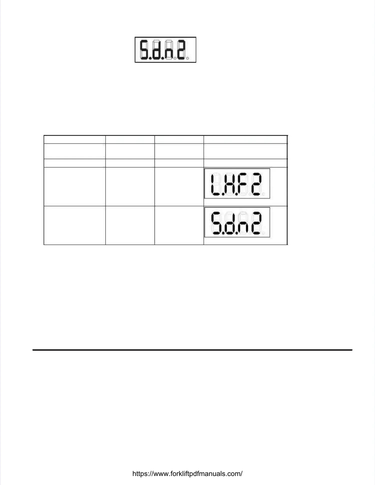
The GPOS / CPOS display indicates the letters ‘Sd’ on the left two digits of the direction/positionThe GPOS / CPOS display indicates the letters ‘Sd’ on the left two digits of the direction/position
indication.indication.
Shifter LeverShifter Lever
The main interface with the driver is the sThe main interface with the driver is the shift leverhift lever. . It allows selecting the driving direction and theIt allows selecting the driving direction and the
different ranges. different ranges. The shift lever output The shift lever output signals serve as inputs fsignals serve as inputs for the APC.or the APC.
For automatic mode, the shift lever position will limit the gear in which the controller is allowed to shift to.For automatic mode, the shift lever position will limit the gear in which the controller is allowed to shift to.
Mode IdentificationMode Identification
The above modes are identified as follows:The above modes are identified as follows:
MMooddee DD––lleedd EE––lleedd DDiissppllaayy
NNoorrmmaal l ddrriivviinngg OOffff aas s ppeer r eerrrroorr
SSeellf f tteesstt OOnn OOffff ddeessccrriibbeed d iin n 44..1188
LLiimmp p hhoommee OOffff BBlliinnkkiinngg
SShhuut t DDoowwnn OOffff BBlliinnkkiinngg
Diagnostics and GuidelinesDiagnostics and Guidelines
Diagnostics and MaintenanceDiagnostics and Maintenance
GeneralGeneral
Principally there are no specific devices required for first level troubleshooting as the APC incorporatesPrincipally there are no specific devices required for first level troubleshooting as the APC incorporates
several self–test features assseveral self–test features assisting in this process. isting in this process. Nevertheless, use of digital Nevertheless, use of digital multi–meters and simplemulti–meters and simple
tools such as an indicator tools such as an indicator lamp will be required to pinpoint lamp will be required to pinpoint exact causes of problemexact causes of problems. s. More indepthMore indepth
troubleshooting and system tuning involves use of a WIN95 Compatible PC with appropriate software andtroubleshooting and system tuning involves use of a WIN95 Compatible PC with appropriate software and
FLASH parameter programming equipment. FLASH parameter programming equipment. The APC allows recall The APC allows recall and modification of non–volatand modification of non–volatileile
parameters through RS232. parameters through RS232. This wayThis way, customers can, given the necessary equipment, choose to adapt, customers can, given the necessary equipment, choose to adapt
certain parameters to suit their needs. certain parameters to suit their needs. From a maintenance point of viewFrom a maintenance point of view, this is relevant in so , this is relevant in so far that thefar that the
APC allows reading APC allows reading back the (modified) back the (modified) parameters along with parameters along with serial number, part number andserial number, part number and
modification date. modification date. Several PC hosted tools have Several PC hosted tools have been developed to ease the servicbeen developed to ease the service and troubleshootinge and troubleshooting
process.process.
S lf Di ti F tiS lf Di ti F ti
https://www.forkliftpdfmanuals.com/
 Loading...