9C-139C-13TX / TXH / TXB 180S - 400L (Rev. 4/23/07)TX / TXH / TXB 180S - 400L (Rev. 4/23/07)
Self Diagnostic FunctionsSelf Diagnostic Functions
The APC has special circuitry to help verify its operation.The APC has special circuitry to help verify its operation.
Six self–test groups are built into the APC control programs:Six self–test groups are built into the APC control programs:
Display test and Display test and VersionVersion
Digital input testDigital input test
Analogue Analogue input testinput test
Speed sensor testSpeed sensor test
Output testOutput test
Voltage testVoltage test
The ’D’ led isThe ’D’ led is ononwhile operating the APC in diagnostic mode.while operating the APC in diagnostic mode.
NOTE:NOTE:
If during operation in a self–test mode a fault is detected, the E–led flashes to indicate the presence of theIf during operation in a self–test mode a fault is detected, the E–led flashes to indicate the presence of the
fault.fault. Pressing S–button (F4) for awhile, however in this case, Pressing S–button (F4) for awhile, however in this case, will not reveal the fault code.will not reveal the fault code.
Self Test OperationSelf Test Operation
Self–test mode is activated by pressing the ‘Self–test mode is activated by pressing the ‘S’S’ switch (F4) on the APC front panel while powering up theswitch (F4) on the APC front panel while powering up the
APC.APC.
Switching off the power of the APC is the only way to leave the self–test mode.Switching off the power of the APC is the only way to leave the self–test mode.
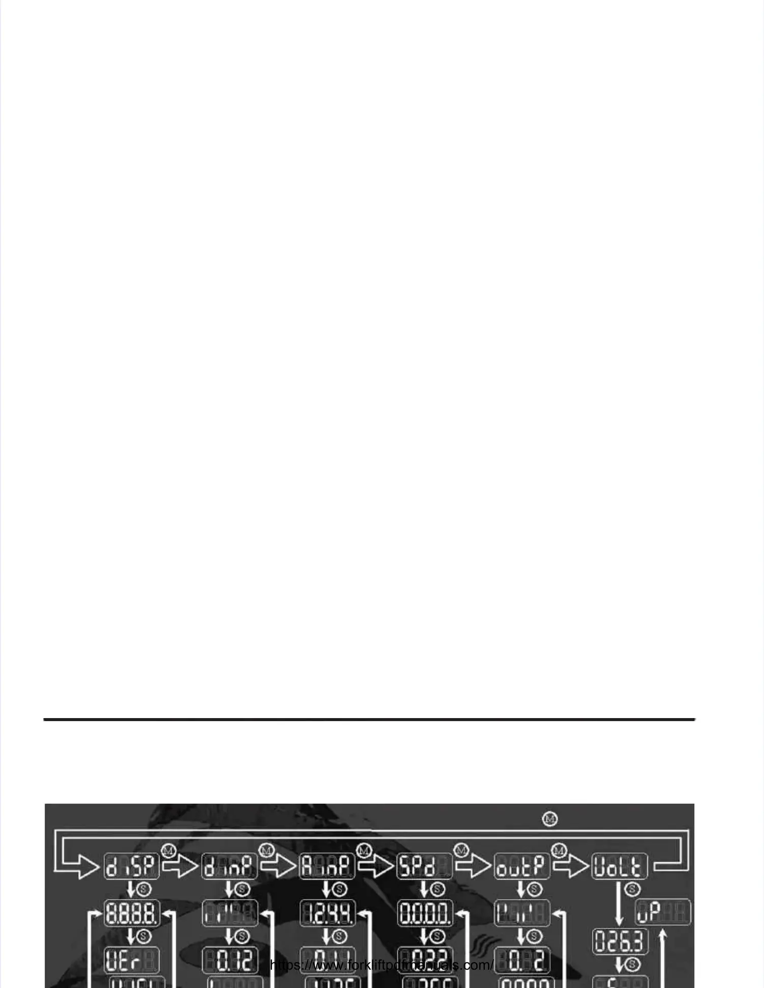
The available information is organized as groups of related displays.The available information is organized as groups of related displays.
Generally, each mode’s start display provides an overview of the status of all members of the group.Generally, each mode’s start display provides an overview of the status of all members of the group.
For instance, the start display of the input test mode cryptically shows the level of each input and theFor instance, the start display of the input test mode cryptically shows the level of each input and the
speed sensor test mode shows the frequency of each sensor channel in kHz (kiloHertz).speed sensor test mode shows the frequency of each sensor channel in kHz (kiloHertz).
Pushing thePushing the ‘M’‘M’switch (F3) selects the next group in the order listed.switch (F3) selects the next group in the order listed.
By pushing theBy pushing the ‘S’‘S’ switch (F4) a list of modes with more detailed information about the selected group canswitch (F4) a list of modes with more detailed information about the selected group can
be looked through.be looked through.
When a new group is selected with theWhen a new group is selected with the ‘M’‘M’ switch (F3), the display always reverts to the overview displayswitch (F3), the display always reverts to the overview display
(i.e., the beginning of the mode–list).(i.e., the beginning of the mode–list).
Pressing a switch (M or S Pressing a switch (M or S / F3 or F4) shortly res/ F3 or F4) shortly reselects the current group or mode. elects the current group or mode. This feature isThis feature is
applicable in all diagnostic–groups.applicable in all diagnostic–groups.
After powering up, After powering up, thethe display testdisplay test is activated.is activated.
 Loading...