TX / TXH / TXB 180S - 400L (Rev. 4/23/07)TX / TXH / TXB 180S - 400L (Rev. 4/23/07)
9C-169C-16
g g yg g y
F4). F4). While pressing the switch, simWhile pressing the switch, similar to the display of digital inputs, the left ilar to the display of digital inputs, the left side of the display givesside of the display gives
information about which input is information about which input is tested; the right side gives tested; the right side gives the matching wire. the matching wire. The displayed value, whenThe displayed value, when
the S switch (F4) is released, is the resistance inthe S switch (F4) is released, is the resistance in ΩΩ. (Ohms).. (Ohms).
NOTE:NOTE:Although the APC also has 4 current sense and Although the APC also has 4 current sense and 3 voltage sense inputs, these are 3 voltage sense inputs, these are notnot
directly accessible through diagnostic displays.directly accessible through diagnostic displays.
The current sense inputs are treated in combination with analog output test modes.The current sense inputs are treated in combination with analog output test modes.
The voltage sense inputs are not yet supported by the diagnostic modes.The voltage sense inputs are not yet supported by the diagnostic modes.
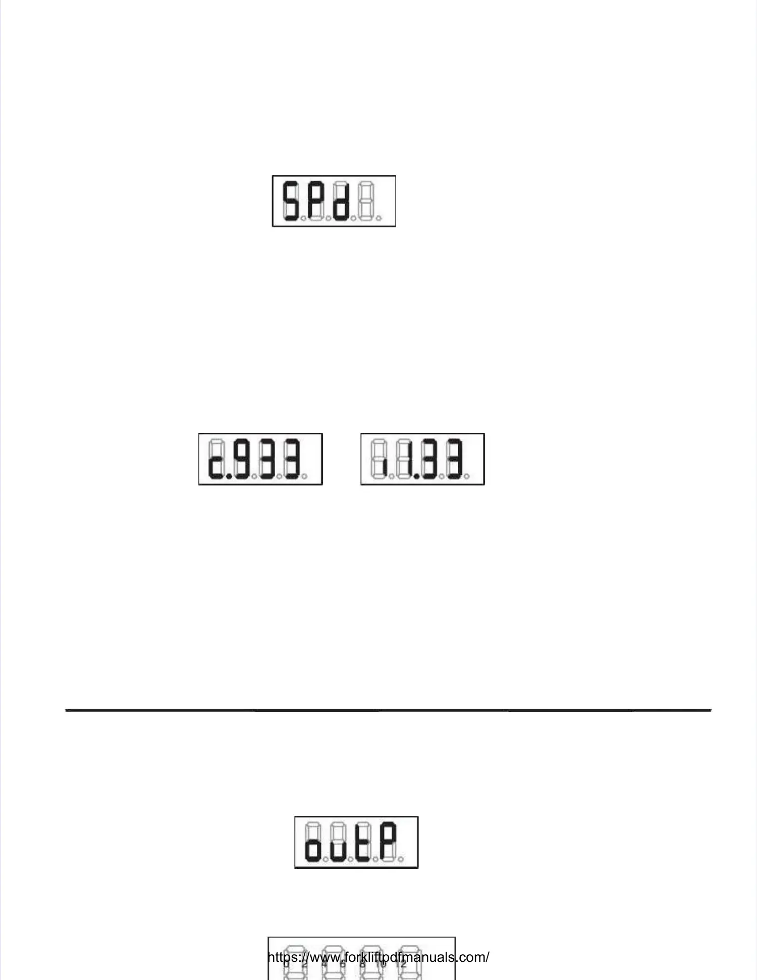
Speed Sensor TestSpeed Sensor Test
When selecting this mode, the display shows:When selecting this mode, the display shows:
When releasing theWhen releasing the ‘M’‘M’switch (F3) again, an switch (F3) again, an overview appears on the displayoverview appears on the display. . The four values, displayedThe four values, displayed
in thousands of Hertz, in thousands of Hertz, are separated by a dot. are separated by a dot. Speeds below 1,000 Hz are Speeds below 1,000 Hz are shown asshown as 00..
Using theUsing the ‘S’‘S’switch (F4) more detswitch (F4) more detailed information concerning the speeds ailed information concerning the speeds is available. is available. While pressingWhile pressing
thethe ‘S’‘S’ switch, the display shows the speed channel number on the left side of the display while theswitch, the display shows the speed channel number on the left side of the display while the
matching wire is shown on the right.matching wire is shown on the right.
Once released, the left digit indicates what type of speed sensor should be connected to this channel:Once released, the left digit indicates what type of speed sensor should be connected to this channel:
cc– for a current sensor (Magneto Resistive Sensor)– for a current sensor (Magneto Resistive Sensor)
ii––for an inductive speed sensorfor an inductive speed sensor
The three other digits and The three other digits and the dot represent the matthe dot represent the matching speed in kHz (kiloHching speed in kHz (kiloHertz). ertz). For instance in theFor instance in the
below examples, the left below examples, the left display indicates a current sdisplay indicates a current speed sensor and a frequency of 933 peed sensor and a frequency of 933 Hz. Hz. The rightThe right
one indicates an inductive sensor generating about 1,330 Hz.one indicates an inductive sensor generating about 1,330 Hz.
After the last channel After the last channel is shown, another press is shown, another press on the ‘S’ on the ‘S’ switch (F4) re–selects the speed switch (F4) re–selects the speed sensorsensor
overview.overview.
Output TestOutput Test
When selecting this mode, the display shows:When selecting this mode, the display shows:
The display shows which The display shows which outputs are active. outputs are active. Similar to the digital input Similar to the digital input test overview screen, test overview screen, eacheach
segment of the display indicates a specific input.segment of the display indicates a specific input.
Different segments can be switched on simultaneously if different outputs are activated simultaneously.Different segments can be switched on simultaneously if different outputs are activated simultaneously.
 Loading...