9C-179C-17TX / TXH / TXB 180S - 400L (Rev. 4/23/07)TX / TXH / TXB 180S - 400L (Rev. 4/23/07)
A blinking A blinking segment indicates a segment indicates a fault at a fault at a certain output.certain output.
In total, there are 11 outputs:In total, there are 11 outputs:
Outputs 0 – 6 are analogOutputs 0 – 6 are analog
Outputs 7 – 9 are STP digitals outputsOutputs 7 – 9 are STP digitals outputs
Output 10 is a STG digital outputOutput 10 is a STG digital output
Information that is more specific can be found while running through the different modes (S switch / F4).Information that is more specific can be found while running through the different modes (S switch / F4).
While pressing the switch, the left side of the display gives information about which output channel isWhile pressing the switch, the left side of the display gives information about which output channel is
tested; the right side gives the matching wire number.tested; the right side gives the matching wire number.
When releasing the switch, the display shows either the actual current in mA (milliAmps), or the logic stateWhen releasing the switch, the display shows either the actual current in mA (milliAmps), or the logic state
of the output (either ‘of the output (either ‘hihi’ or ’lo’).’ or ’lo’).
If an output is currently in fault, its respectIf an output is currently in fault, its respective segment in the overview screen blinks slowlyive segment in the overview screen blinks slowly. . On the outputOn the output
specific screen, the display alternates between the actual state (current value or logic state) and the faultspecific screen, the display alternates between the actual state (current value or logic state) and the fault
type (open / short / curr / oor).type (open / short / curr / oor).
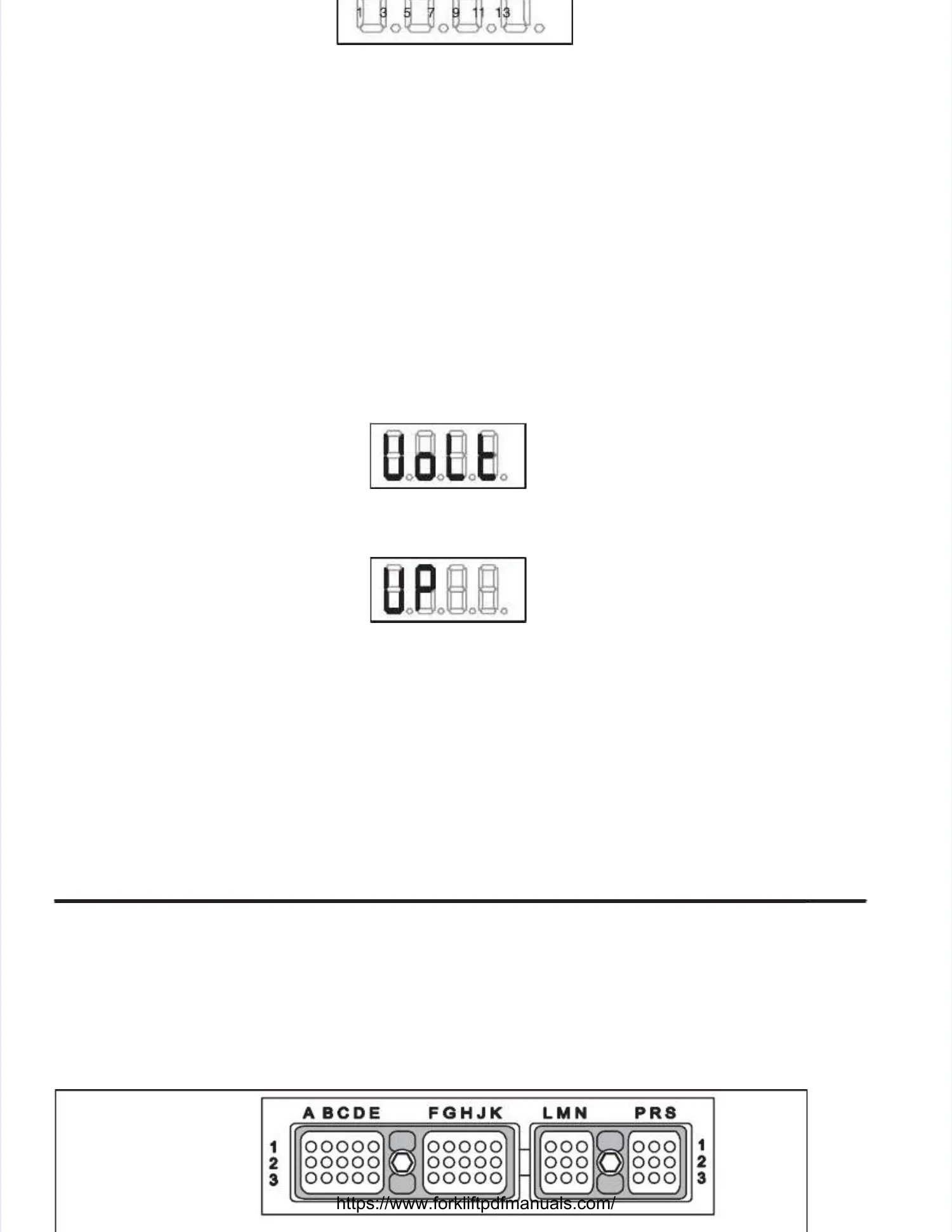
Voltage TVoltage Testest
When selecting this mode, the display shows:When selecting this mode, the display shows:
The displayed value, after the M switch (F3) is released, is theThe displayed value, after the M switch (F3) is released, is the PERMANENT VOLTAGE VpPERMANENT VOLTAGE Vp in Volts asin Volts as
measured on wiremeasured on wire A01A01..
The two other modes of this group areThe two other modes of this group are switched voltage (Vs)switched voltage (Vs) andand sensor voltage (Vsen)sensor voltage (Vsen), also, also
expressed inexpressed inVolVoltsts..
VsVs is measured on wire B12. is measured on wire B12. This power supply input is used to allow tThis power supply input is used to allow the APC to control the power downhe APC to control the power down
process, allowing it to save statistical information in FLASH before actually shutting down.process, allowing it to save statistical information in FLASH before actually shutting down.
VsenVsen is measured off an internally generated voltage regulator and should be near 8.0Vis measured off an internally generated voltage regulator and should be near 8.0V. . It can beIt can be
measured on any unloaded analog input channel (e.g. ANI0 on A11). measured on any unloaded analog input channel (e.g. ANI0 on A11). The Vsen voltage is The Vsen voltage is used as aused as a
reference for the analog inputs.reference for the analog inputs.
Connector layout :Connector layout :
Rear view on theRear view on the
controller connectorcontroller connector
J154J154 J155J155
 Loading...