TX / TXH / TXB 180S - 400L (Rev. 4/23/07)
TX / TXH / TXB 180S - 400L (Rev. 4/23/07)
1-41-4
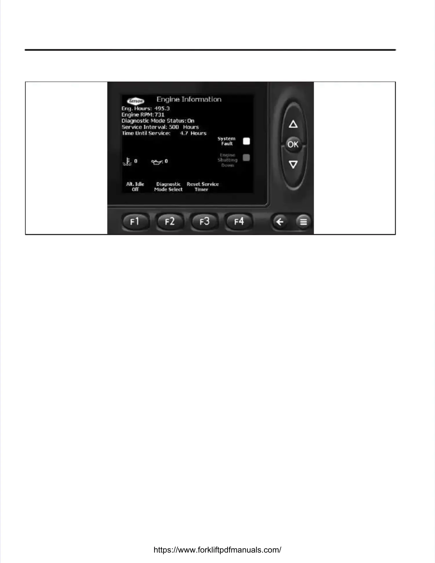
Illustration 1-4. Illustration 1-4. Engine Engine Diagnostics Diagnostics IconsIcons
Calibration Of Electronic Accelerator Pedal ToCalibration Of Electronic Accelerator Pedal To
ECM Of Engine.ECM Of Engine. The The Cummins Cummins QSB6.7 QSB6.7 engineengine
uses an electronic accelerator to control engineuses an electronic accelerator to control engine
speed. speed. Each time Each time the accelerator the accelerator pedal ispedal is
changed, disconnected and the ignition switch ischanged, disconnected and the ignition switch is
turned on, or ECM (Electronic Control Module) isturned on, or ECM (Electronic Control Module) is
changed out, the accelerator pedal must be cali-changed out, the accelerator pedal must be cali-
brated to brated to the ECM. the ECM. Calibration procedures Calibration procedures are asare as
follows:follows:
1.1. ApplApply the py the parkarking bing brakrake, ple, place tace the shhe shiftifter iner in
neutral, and turn the ignition switch to the Igni-neutral, and turn the ignition switch to the Igni-
tion position (first click).tion position (first click).
2.2. Cycle Cycle the the accelaccelerator erator pedal pedal throuthrough igh its ts fullfull
range of travel three times.range of travel three times.
3.3. TurTurn the n the ignitignition swion switch itch to thto the Off e Off positiposition foon forr
at least 30 seconds.at least 30 seconds.
Engine Fault Code Warning BoxEngine Fault Code Warning Box (Illustration(Illustration
1-5)1-5).. An engine fault An engine fault code warning box code warning box will be dis-will be dis-
played on the Engine Information screen when anplayed on the Engine Information screen when an
engine fault code engine fault code is active. is active. This warning box This warning box dis-dis-
plays the number of plays the number of the active fault code. the active fault code. TTo clearo clear
the warning box after recording the fault codethe warning box after recording the fault code
number, depress number, depress the F2 (OK) the F2 (OK) button. button. Once theOnce the
warning box has been cleared, the fault code willwarning box has been cleared, the fault code will
have to be flashed out in the Diagnostic Mode if ithave to be flashed out in the Diagnostic Mode if it
was not recorded (refer towas not recorded (refer to Diagnostic FaultDiagnostic Fault
CodesCodes).).
Engine Diagnostic IconsEngine Diagnostic Icons(Illustration 1-4)(Illustration 1-4).. TheThe
engine diagnostic icons, displayed by the Taylorengine diagnostic icons, displayed by the Taylor
Integrated Control System (TICS) display moduleIntegrated Control System (TICS) display module
on the Engine Information Screen, are used toon the Engine Information Screen, are used to
alert the operator of engine related problems.alert the operator of engine related problems.
Each diagnostic icon’s function is described asEach diagnostic icon’s function is described as
follows:follows:
1.1. Yellow IconYellow Icon(System Fault)(System Fault).. This icon will beThis icon will be
displayed during a displayed during a non-fatal system non-fatal system error. error. TheThe
engine can still be run, but the fault should beengine can still be run, but the fault should be
corrected as soon as possible.corrected as soon as possible.
NOTE:NOTE: In the In the diagnostic mode, diagnostic mode, the yellow the yellow iconicon
will flash after the red icon completes the three-will flash after the red icon completes the three-
digit fault code.digit fault code.
2.2. Red IconRed Icon(Engine Shutting Down)(Engine Shutting Down).. This This iconicon
will be displayed when the engine needs to bewill be displayed when the engine needs to be
shut off before permanent damage occurs toshut off before permanent damage occurs to
the engine. the engine. Should the Should the red icon red icon be displayedbe displayed
while operating, the fault can be engine disab-while operating, the fault can be engine disab-
ling after ling after approximately 32 approximately 32 seconds. seconds. ShouldShould
the engine shut down due to the severity ofthe engine shut down due to the severity of
the fault, it can be restarted and will run forthe fault, it can be restarted and will run for
approximately 32 approximately 32 seconds. seconds. The engine The engine willwill
run for approximately 32 seconds each time itrun for approximately 32 seconds each time it
is restarted. is restarted. There are no There are no limits on limits on the num-the num-
ber of times the engine may be restarted.ber of times the engine may be restarted.
NOTES:NOTES:
The engine should be shut off as soon as itThe engine should be shut off as soon as it
can be shut off can be shut off safelysafely. . The engine shouldThe engine shouldnotnot
be run until be run until the fault is corrected.the fault is corrected.
This icon is also used to flash out the faultThis icon is also used to flash out the fault
code number in the diagnostic mode.code number in the diagnostic mode.
 Loading...