TX / TXH / TXB 180S - 400L (Rev. 4/23/07)TX / TXH / TXB 180S - 400L (Rev. 4/23/07)
6-66-6
1.1. TurTurn the n the ignitignition keion key to y to the the IgnitiIgnition pon positioosition.n.
2.2. If thIf the cire circuit cuit breakebreaker is tr is trippedripped, res, reset thet the circe circuituit
breaker.breaker.
3.3. If If the the circucircuit it breakebreaker imr immediatmediately ely retripretrips,s,
remove all wires from the output side (loadremove all wires from the output side (load
side) of the circuit breaker.side) of the circuit breaker.
4.4. Reset Reset the the circucircuit it breakebreakerr. . If If the the circucircuit it breakebreakerr
retrips, the circuit breaker is defective andretrips, the circuit breaker is defective and
must be replaced.must be replaced.
5.5. If tIf the cihe circuit rcuit breakbreaker maer maintainintains a s a set sset state, tate, oneone
of the of the output circuitoutput circuits is s is shorted. shorted. ReconnectReconnect
the wires one by one to the output side (loadthe wires one by one to the output side (load
side) until tside) until the circuit he circuit breaker trips. breaker trips. Trouble-Trouble-
shoot the circuit of the wire, that tripped theshoot the circuit of the wire, that tripped the
circuit breaker, for a short.circuit breaker, for a short.
6.6. IsolatIsolate and e and removremove the the she short ort from from the the circucircuit.it.
Automatic 90 amp Automatic 90 amp Circuit BreakerCircuit Breaker.. The auto-The auto-
matic 90 amp circuit breaker is located on the rightmatic 90 amp circuit breaker is located on the right
side of engine. side of engine. It will automaticIt will automatically reset itself ally reset itself ifif
g p pg p p
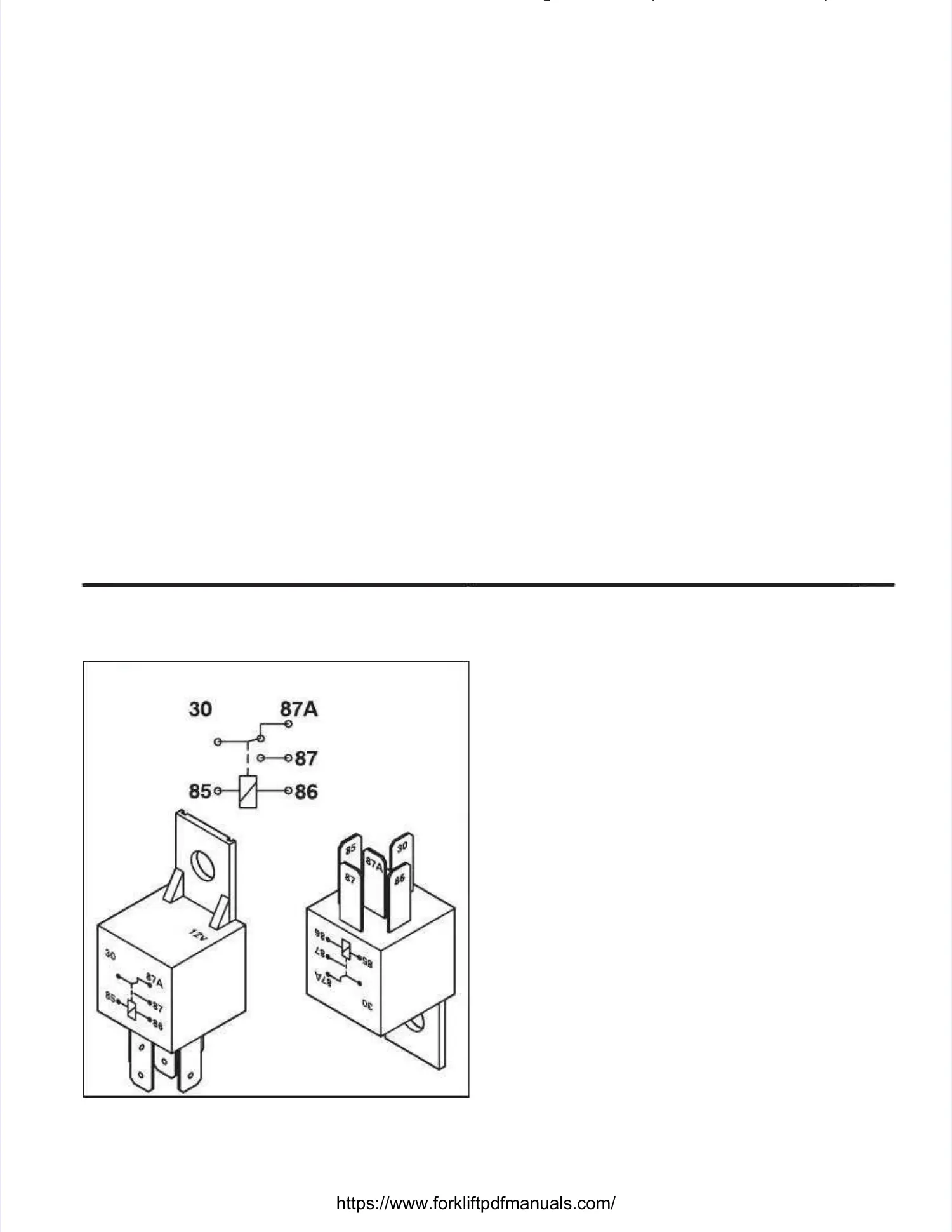
30, 87, and 30, 87, and 87A. 87A. In a de-energized In a de-energized state, ensurestate, ensure
that pins 30 and 87A have continuity betweenthat pins 30 and 87A have continuity between
them. them. With an ohmmetWith an ohmmeter, er, check the resistcheck the resistanceance
between pins between pins 30 and 30 and 87a. 87a. The ohmmeter The ohmmeter shouldshould
indicate a reading indicate a reading of 0 - of 0 - 40 ohms. 40 ohms. Energize theEnergize the
relay and check the resistance between pins 30relay and check the resistance between pins 30
and 87. and 87. The ohmmeter The ohmmeter should indicate should indicate a readinga reading
of 0 - 40 ohmof 0 - 40 ohms. s. If these two If these two checks are good, checks are good, thethe
relay is good.relay is good.
Single-Pole, Single-Pole, Single-ThrowSingle-Throw, Maintain Contact, Maintain Contact
Switches.Switches. A switch A switch is designed wis designed with the purposeith the purpose
of controlling an electrical circuit by completing orof controlling an electrical circuit by completing or
opening the circuit. opening the circuit. With an ohmmeterWith an ohmmeter, check t, check thehe
resistance between the contact points of theresistance between the contact points of the
switch. switch. With the With the switch closed switch closed (completing the(completing the
circuit), the ohmmeter reading should indicate 0 -circuit), the ohmmeter reading should indicate 0 -
40 ohms. 40 ohms. With the With the switch open (opening switch open (opening the cir-the cir-
cuit), the ohmmeter cuit), the ohmmeter reading should be infinityreading should be infinity. . IfIf
the above checkthe above checks are good, ts are good, the switch is he switch is good. good. IfIf
any of the above checks fail, the switch is bad andany of the above checks fail, the switch is bad and
must be replaced.must be replaced.
Normally ClosedNormally Closed
Contact (when relayContact (when relay
is de-energized)is de-energized)
Normally OpenNormally Open
Contact (when relayContact (when relay
is de-energized)is de-energized)
CommonCommon
ContactContact
Illustration 6-4. Illustration 6-4. SPSP, ST 30 am, ST 30 amp Relayp Relay
Single-Pole, Double-Throw, Momentary RockerSingle-Pole, Double-Throw, Momentary Rocker
Switches.Switches. This type This type of switch of switch operates on theoperates on the
principle that the circuit is closed only when theprinciple that the circuit is closed only when the
switch is held in switch is held in the closed state. the closed state. Once the switchOnce the switch
is released, theis released, the circuit will open.circuit will open. This switchThis switch isis
simplest way to prove the solenoid coil good is tosimplest way to prove the solenoid coil good is to
energize the solenoid and then, with a metalenergize the solenoid and then, with a metal
object, touch the nutobject, touch the nutthat secures the coil to thethat secures the coil to the
cartridge. cartridge. The magnetic The magnetic field generated field generated when thewhen the
coil becomes an electromagnet will be significantcoil becomes an electromagnet will be significant
enough to pull the metal object to the nut (someenough to pull the metal object to the nut (some
solenoids employ a metal nut encased in plasticsolenoids employ a metal nut encased in plastic
and will require removal in order to detect theand will require removal in order to detect the
magnetic field). magnetic field). This will This will prove the cprove the coil good; how-oil good; how-
ever, tever, the armature may be he armature may be stuck. stuck. If the hydraulicIf the hydraulic
circuit is still defective at this point, remove the coilcircuit is still defective at this point, remove the coil
and cartridge. and cartridge. Now energize Now energize the coil, the coil, the arma-the arma-
ture inside the ture inside the cartridge should shifcartridge should shift. t. If the armIf the arma-a-
ture inside the cartridge did not shift and the coil isture inside the cartridge did not shift and the coil is
magnetized, replace the cartridge.magnetized, replace the cartridge.
Exercise care not to reverse polarity becauseExercise care not to reverse polarity because
some solenoids employ internal diodes which cansome solenoids employ internal diodes which can
be destroyed be destroyed when the when the polarity is polarity is reversed. reversed. TheThe
solenoids employed on the transmission controlsolenoids employed on the transmission control
valve contain diodes. valve contain diodes. The black wThe black wire of the ire of the coilcoil
connects to the ground side of the circuit while theconnects to the ground side of the circuit while the
red wire goes to the positive side of the circuit.red wire goes to the positive side of the circuit.
DiodesDiodes(Illustration 6-5)(Illustration 6-5).. Diodes Diodes are are one-wayone-way
conductors tconductors that provide hat provide isolation. isolation. Current flowCurrent flow
through a diode through a diode is from is from anode to canode to cathode. athode. TheyThey
are easily proven good by using an ohmmeter.are easily proven good by using an ohmmeter.
When using the ohmmeter, place the leads of theWhen using the ohmmeter, place the leads of the
ohmmeter on the opposite ends of the diode.ohmmeter on the opposite ends of the diode.
Observe the Observe the ohmmeter reading. ohmmeter reading. Then reverse Then reverse thethe
ohmmeter leads on the ends of the diode.ohmmeter leads on the ends of the diode.
Observe the Observe the ohmmeter reading. ohmmeter reading. The ohmmThe ohmmetereter
 Loading...