ES100 ESS Unit user manual
5
Table 2-3 Interface Definition
Connect to battery positive output cable or
positive parallel cable
OFF/ON button, must be on the "ON" state
when in use
The number of green lights on shows the
remaining battery power. See Table 2-6 for
details.
Red light flashes when an alarm occurs. Red
light is always on during protection status.
After the protection is released, it can be
automatically closed.
Green light flashes during standby and
charging mode. Green light is always on
when the battery is under discharging.
Communication cascade port, support CAN
Communication cascade port, support 485
Connect to battery negative output cable or
parallel negative cable
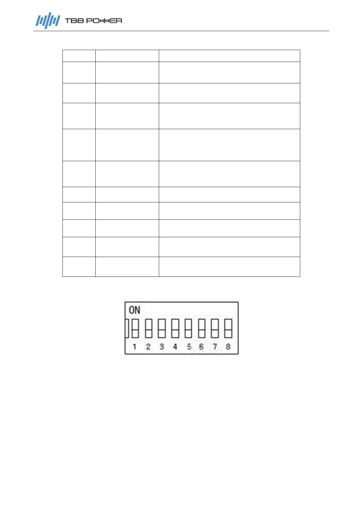
2.2.2 Address
DIP switch bit1 to bit8 definition: bit1~bit5 is used to set the slave address or the number of slaves
in parallel according to the master and slave status; bit8 is used to set the mark of the master and
slave; bit6~bit7 are reserved bits.
Slave setting: bit1~bit5 are used to set the slave address. According to the device sequence, the
slave address range is from 1 to 31. bit8 is fixed to OFF. Please refer to the slave setting table for
detailed dialing code.
Host setting: bit1~bit5 are used to set the number of slaves in parallel. bit8 is fixed to ON. Please
refer to the host setting table for detailed dialing code.
When the battery packs are connected in parallel, the master battery and the slave battery can
communicate with each other through the RS485 interface, to get the information of the entire
battery system. The battery can communicate with the inverter via CAN interface.
 Loading...