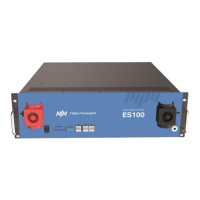
ES100 ESS Unit user manual
12
3.1.5 Engineering coordination
Attention should be paid to the following items before construction:
Power cable specification.
The power cable specification shall meet the requirements of maximum discharge current for
each product.
Mounting space and bearing capacity.
Make sure that the battery has enough room to install, and the battery rack and bracket have
enough load capacity.
Wiring
Make sure the power cables and ground wires are installed reasonably, to prevent them from
being short-circuited, flooded, and corroded.
3.2 Equipment installation
Table 3-3 Installation steps
Confirm that the ON/OFF switch on the front panel of battery is
in the “OFF” state to ensure no live operation.
1. Cabinet placement position determination
2. Pre-install the top cable harness
3. Battery module installation
1. Ground cable installation
2. Battery module parallel cables installation
3. Battery module all positive cables installation
4. Battery module all negative cable installation
5. Internal CAN communication interface connection
1. Press the ON/OFF switch to the "ON" state
2. BMS system power-on activation
3. Check the system output voltage
1. Connect all positive & all negative cables of the
battery system to the inverter
2. Connect the external CAN communication cable to the
inverter