EasyManua.ls Logo

TBB power ES100 - 3. Installation and Configuration; 3.1 Installation Preparation and Requirements

TBB power ES100
24 pages
Print Icon
To Next Page IconTo Next Page
To Previous Page IconTo Previous Page
Loading...
ES100 ESS Unit user manual
7
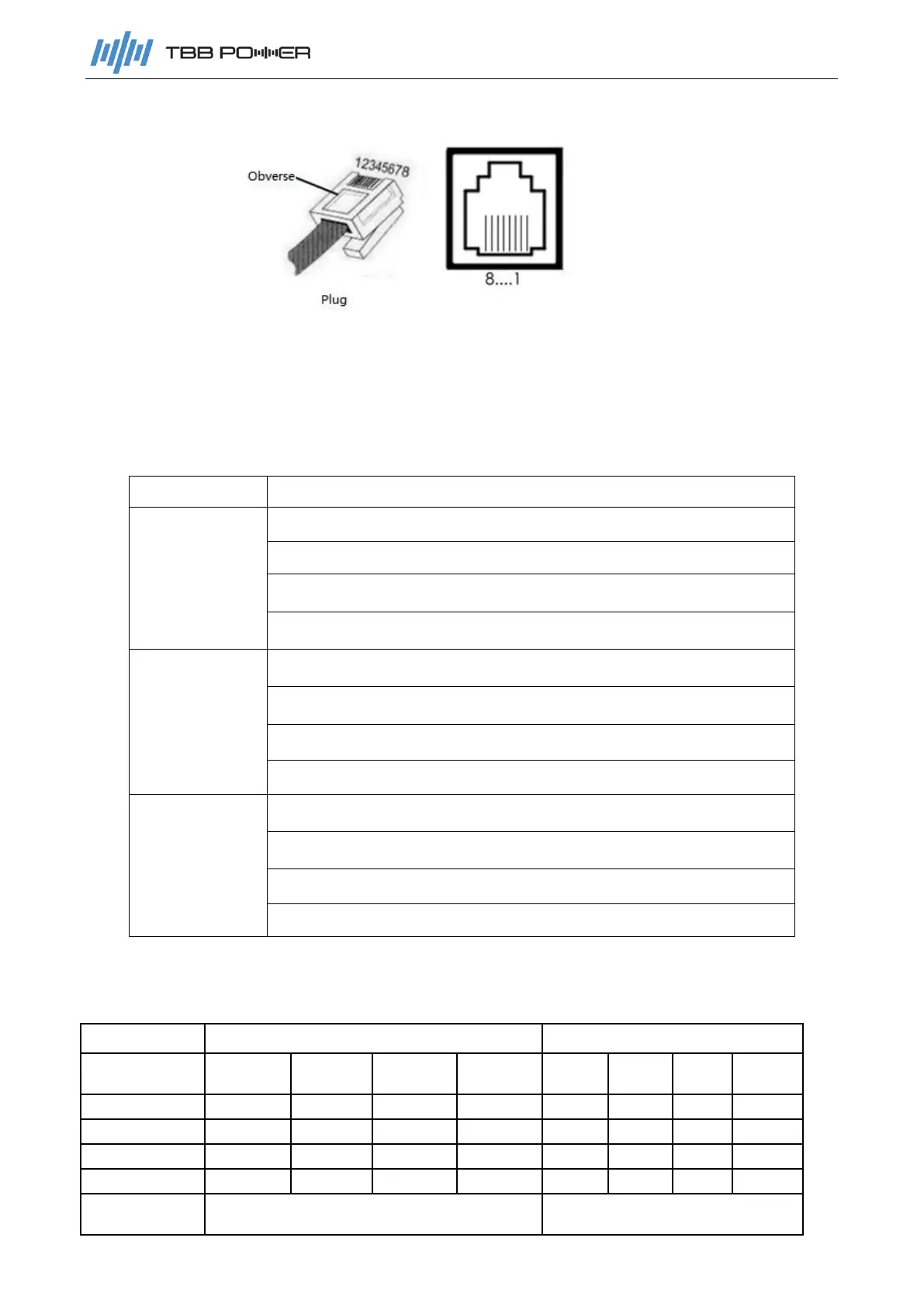
2.2.3 Communication Port Definition
The product provides three RJ45 connectors respectively for one CAN port and two RS485
communication ports. All pins of the two connectors RS485-1 and RS485-2, are connected in
parallel, so their interface definitions are completely the same. Table 2-6 defines the pins of each
interface.
Table 2-6
Port
Description
CAN
PIN4:CANH
PIN5:CANL
PIN138:NC
PIN267:NC
RS485-1
PIN27:485-1A
PIN138:485-1B
PIN6:485-2A
PIN5:485-2B
RS485-2
PIN27:485-1A
PIN138:485-1B
PIN6: 485-2A
PIN5: 485-2B
2.2.4 SOC light display and corresponding battery capacity
Table 2-7
Status
Charging
Discharging
Capacity
indicator
L1
L2
L3
L4
L1
L2
L3
L4
0~25%
flashing
OFF
OFF
OFF
ON
OFF
OFF
OFF
25~50%
ON
flashing
OFF
OFF
ON
ON
OFF
OFF
50~75%
ON
ON
flashing
OFF
ON
ON
ON
OFF
75~100%
ON
ON
ON
flashing
ON
ON
ON
ON
Running
indicator
ON
flashing