Do you have a question about the TBB Energier Pro Series and is the answer not in the manual?
Provides legal limitations on warranty and liability for the information in the manual.
Introduction to the user manual for the Energier pro Inverter Charger Combination.
Instructions for qualified personnel regarding dangerous voltages and high temperatures.
Precautions for indoor use, ventilation, cable selection, and placement near inflammable goods.
Safety measures for handling batteries, avoiding sparks, and removing metal items.
Overview of the Energier pro Inverter Charger Combination and its capabilities.
Details on the inverter's pure sine wave output and high surge power capability.
Features of the built-in charger, including powerful charging and temperature compensation.
Details on the 3-5A floater charger for mobile applications or starter battery charging.
Explanation of the AC transfer switch function and UPS capabilities.
Offers charging profiles for various battery chemistries like AGM, GEL, Flooded, Lithium.
Program for improving Flooded battery performance by equalizing cells.
User-configurable low voltage disconnect levels for battery protection.
Mode for handling weak grid supplies with low voltage drops.
Configuration for solar hybrid systems with DC priority.
Configuring the unit for unstable generator inputs.
Reduces no-load power consumption by switching off under low load conditions.
Functionality to start the generator automatically based on battery status.
Allocates power from limited AC sources to avoid overloading.
Optional remote control panel for monitoring and configuration via RS485.
Remote module for monitoring load, battery state, and system info.
Connects Grid and Diesel Generator as AC input sources, managing seamless transfer.
Features for remote equipment control (input) and load management (output).
Mode for charging only, protecting the battery from unintentional discharge.
Communication port for connecting to Vision Lite or Rapconfig for monitoring and control.
Parameters configurable via PC, including charging, input, and battery modes.
Hardware and software protections against overload, overheat, and short circuits.
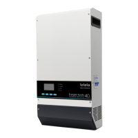
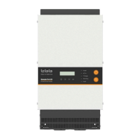
Visual representation of the Energier pro Inverter Charger Combination unit.
Image and identification of the RCF remote module.
Image and identification of the Vision Lite control center.
Image and identification of the AGS Automatic Generator Start module.
Image and identification of the TAI Twin AC input module.
Dimensional drawings for Energier pro Inverter Charger Combination models.
Dimensional drawings for the RCF remote module.
Dimensional drawings for the Vision Lite control center.
Dimensional drawings for the AGS Automatic Generator Start module.
Dimensional drawings for the TAI Twin AC input module.
Identifies connection ports and switches on the front panel of the unit.
Identifies connection ports and configuration options on the central panel.
Configuring the charging current based on battery capacity using the clock switch.
Configuration of weak grid mode using DIP Switch 1 for low voltage input quality.
Configuration of solar mode using DIP Switch 2 for solar hybrid systems.
Setting low voltage protection levels using DIP Switch 3 for system safety.
Selecting battery types (AGM, GEL, LFP, Flooded, OPzS, Lead-Carbon) via DIP Switch 4-5.
Performing equalization charging for Flooded and OPzS batteries using DIP Switch 6.
Setting power save mode using DIP Switch 7 to reduce standby consumption.
Configuring weak grid and GEN modes using DIP Switches 1 and 8.
Setting the AC input current limit via the RCF remote.
List of items included in the product packaging.
Recommended environmental conditions for installing the unit.
Minimum recommended wire sizes for AC and DC connections.
Ensuring correct DC voltage, proximity to batteries, and avoiding parallel AC sources.
Steps for securely mounting the inverter unit vertically on a wall.
Detailed instructions for connecting DC cables to the unit, including polarity and terminal identification.
Instructions for connecting the TS temperature sensor.
Instructions for connecting the VS voltage sensor.
Steps for installing and connecting the RCF remote controller.
Steps for installing and connecting the Vision Lite control center.
Wiring guide for installing and connecting the AGS module.
Instructions for installing and connecting the TAI unit for dual AC inputs.
Verifying DC input voltage, polarity, and AC connections before operation.
Procedure for setting the AC input parameters.
Functionality of the main switch for ON and CHG ONLY modes.
Procedure for switching on the inverter and powering loads.
Procedure for switching on the charger and operating in bypass mode.
Procedure for switching off AC input and transferring to inverter mode.
Details on the bulk charging stage, indicators, and LED status.
Details on the absorption charging stage, indicators, and LED status.
Details on the floating charging stage, indicators, and LED status.
Setting and operation of the power saving mode.
Adjusting the standby level entry for power saving mode.
Instructions and precautions for performing de-sulphation charging.
Table detailing LED status and audible alarms for various functions and fault conditions.
Table detailing LED status for AC in, Charger, Inverter, Fault, and other indicators.