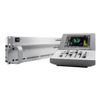
FRONT PANEL OVERVIEW
9
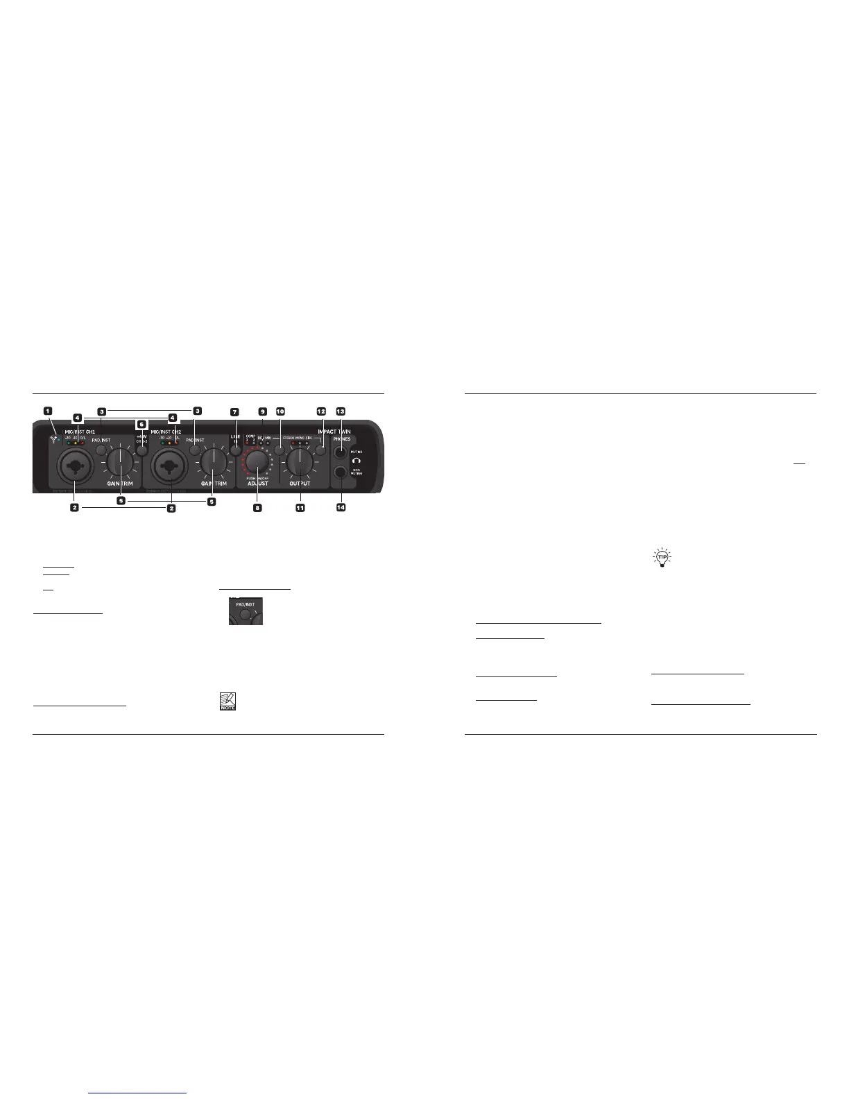
1 FireWire/Power LED Indicator
When Impact Twin is hooked up via FireWire, the
blue LED can indicate the following states:
Steadily lit: Sufficient power
Flashing: Uploading firmware, hardware error or
FireWire communication error.
Off: The Impact Twin cannot establish
a connection to the driver, maybe
because the driver is not installed.
Device Identification:
The blue LED will flash a couple of times when the
“Impact Twin” tab in the control panel is selected.
This comes handy if you have more than one TC
audio interface connected to your computer. In this
case, you can use the device tab to identify the audio
interface.
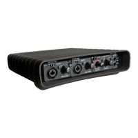
2 Mic/Inst CH1/CH2 on Combo XLR/Jack
ComboXLR/jackinputs.BothXLRand1/4inchjacks
can be used with this connector.
TheXLRConnection(Balanced)
Connect a microphone, and your signal is processed via
the IMPACT™ mic pre-amps.
– Whenusingcondensermicrophones,activate
phantom power (see section 6 on the following page).
– TheInputLEDs(4)indicatetheleveloftheinput
signal. If the red O/L LED (overload) is lit, your signal
is too “hot”, and you should press “PAD/INST” to
attenuatethesignalby20dB.
The 1/4 Jack Connection
– PressPAD/INSTtoactivatethiscircuit.
The 1/4 “jack part” of the combo connector is a
high-quality Hi-Z circuit that has been designed
especially for connecting a passive guitar pick-up system
(e.g. Strat-type) directly. The jack inputs on the front
panel are unbalanced. If you wish to use balanced
equipment using TRS jacks, you should connect them
via the line inputs on the rear panel.
Important!
If you use the 1/4 jack part of the Combo jack/
XLRconnection,thePAD/INSTselectormustbe
set to “In” position.
FRONT PANEL OVERVIEW
8
3 PAD/INST Selectors
The PAD/INSTRUMENT selector can attenuate the
inputsensitivityby20dB.Ifyoucannotattenuate
thesignalsufficientlyusingtheGAINTRIMknob,
youshouldusethe-20dBposition.Thisisnormally
required when connecting line-level instruments.
4 Input LEDs
ThreeInputlevelindicators:-30dB,-10dBand“O/L”.
The input LEDs indicate the level of the input signal.
If the O/L LED (“Overload”) is lit, your signal might
be too hot, and you should lower the input by using
theGAINTRIMknoborthe20dBPADswitch.O/L
indication should be used as a guide only. For more
precise level indication, please use the level meters in
the control panel software.
5 Gain/Trim
Use this control to set the appropriate input level (see
previous paragraph).
6 Phantom Power +48V
Whenthisswitchispressed,theXLRpartofthe
ComboXLR/Jackconnectionsfeatures+48V
phantom power. Phantom power is used to power
line-drivers and condenser microphones.
There are three main types of microphones:
Condenser microphone: Phantom power is required
(except for some models that use proprietary power
supplies or built-in batteries). Please check the
microphone manufacturer’s specifications for details.
Electrodynamic microphone: Here, phantom power is
not required (but does no harm to the microphone).
Ribbon microphones: Phantom power could
damage these microphones! Please refer
to the microphone’s documentation or the
manufacturer’s support information.
Only condenser type microphones require
phantom power. You can, however, combine e.g. a
condenser microphone on channel 1 with a standard
electrodynamic microphone (e.g. a Shure SM57) on
channel 2 without problems. You can also activate
phantom power and use a condenser microphone on
one of the inputs and connect a guitar using a 1/4
jack to the other input, as the phantom power only
goestotheXLRpins.
7 Line In – Ch 1/2 Input Selector
Use this switch to select either front panel or rear
panel inputs for channels 1/2.
Rear panel inputs are line inputs.
WhenyouselectLineIn1+2,you’llseetheTCNear
mixerpageconvenientlycollapsetheChannels1+2
section.
Connect any secondary device that you don’t
use in music production to Line inputs 1/2 on the
rear panel. Use the “Line In” switch to alternate
between front and rear panel inputs.
8/9/10 ADJUST Dialer
The ADJUST dialer can be used to adjust the
function selected with the FUNCTION selector (10):
– Compressionamountonchannel1
– Compressionamountonchannel2
– Reverbamount/Decaytime
– DAWmixinput/100%DAW
The selected function is indicated by the four LEDs (9).
ADJUSTDialer–PushFunction
A few extra features are built in the ADJUST knob and its
push function.
Example #1 – Compression Mode:
– Pressthefunctionselector(10)andselect
compression mode.
 Loading...