11
– NowturntheADJUSTdialertosetthecompression
amount.
– PresstheADJUSTknoboncetobypassthe
compressor.
– TurningtheADJUSTdialeragainwillautomatically
reactivate the compressor, and the compression
amountcanbeadjustedagainstartingfrom0%.*
*Thisfeaturepreventsyoufromaccidentlysettingan
extreme compression amount while the compressor is
bypassed.
Example #2 – Compression Mode A/B Listening:
– Pressthefunctionselector(10)andselect
compression mode.
– NowturntheADJUSTdialertosetthecompression
amount.
– PresstheADJUSTknobseveraltimestocompare
compressedanduncompressedsignal(A/Blistening).
– IfyouturntheADJUSTknobwhilethecompressoris
“on” you will now adjust from the current compression
amount.
Example #3 – using ADJUST to control Decay time and
and Reverb amount
– Pressthefunctionselector(10)andselect“REV”.
– NowpresstheADJUSTencodertotogglebetween
letting the encoder control Reverb amount or decay
time.
11 Output Level Knob
Sets the output level of analog outputs 1-2 and of the
headphone outputs.
12 Listening Mode selector: Stereo / Mono / Side
This feature allows you to listen not only in stereo
mode (standard), but also monitor the mono and side
components separately.
STEREO: You are listening to your signal in stereo
(this is the default setting).
MONO: Listen to your signal in mono. The left and
right channel are summed and sent to both outputs.
SIDE: Listen only to the SIDE component of your
signal (in this mode, the M/S decoding algorithm is
active).
Monitoring the side component is especially
interesting when comparing a data-reduced format
(such as MP3 or AAC) to a linear signal or to a
data-reduced signal at a different bit rate, since
artifacts from MP3 or AAC encoding are highly
exposed in the side component.
13 Phones – Muting
When you connect a set of headphones to this jack,
mainoutputswillbemuted.*
14 Phones – Non-muting
When you connect a set of headphones to this jack,
thesignalisstillpassedtothemainoutputs.*
*BothPhonesoutputscanbeused
simultaneously.
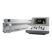
FRONT PANEL OVERVIEW
10
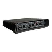
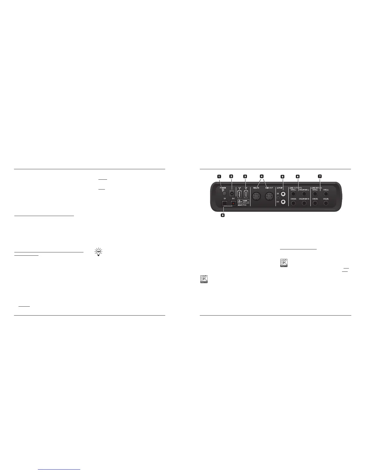
REAR PANEL OVERVIEW
1 Power Switch
On/off switch for the unit.
2 Power In Jack
Impact Twin can be bus-powered from the computer’s
FireWire port if your computer supplies bus power.
Check your computer’s specifications. If more than
one bus-powered audio interface is used or if your
computer delivers insufficient power on the FireWire
port, use the supplied 12 VDC power supply.
3 FireWire Connectors
IEEE 1394 connectors for connecting to a computer
and/or linking multiple Impact Twin units. Impact Twin
canbebus-powered*fromthecomputer’sFireWire
port. Check your computer’s specifications.
Before plugging the FireWire connectors, make
sure that plugs are positioned correctly.
* Please read the manual section on bus-power.
4 MIDI In/Out
Standard MIDI In/Out jacks.
5 S/PDIF – Digital In/Out – Coaxial
24 bit digital in/out on S/PDIF. Instead of operating
these digital connectors as input and output, you can
also use them to insert e.g. an external digital effects
unit–andusethisasasendeffectinthedirect
monitoring audio path.
6 Line Outputs (balanced)
1/4 inch TRS jack outputs for:
– MainLeft(CH1)andMainRight(CH2)
– Left(CH3)andRight(CH4)
When connecting the Main outputs to a device
(e.g. active speakers) with unbalanced inputs,
“ground” and “cold” must be connected. On XLR
type plugs, these are the pins 1 and 3. On Jack
type plugs, these are the “sleeve” and “ring”
parts.
7 Line Inputs (balanced)
– Ch1(Left) – Ch3(Left)
– Ch2(Right) – Ch4(Right)
8 DI/DO – ADAT/TOS In/Out
Optical S/PDIF or ADAT for up to 8 channels of digital
I/O, depending on format and sample rate.
 Loading...