INTERFACING TO SPDIF 37
On most consumer equipment, SPDIF or IEC 958 is used instead of AES/EBU. With some
limitations, that type of signal can often be interfaced to the UNIT•Y card, if you follow the
guidelines given below.
UNIT•Y output to SPDIF input
Some SPDIF equipment may reject a signal because the Status Bits are set according to
the AES/EBU specification, but in most cases Pro status is accepted, and a signal may be
transferred.
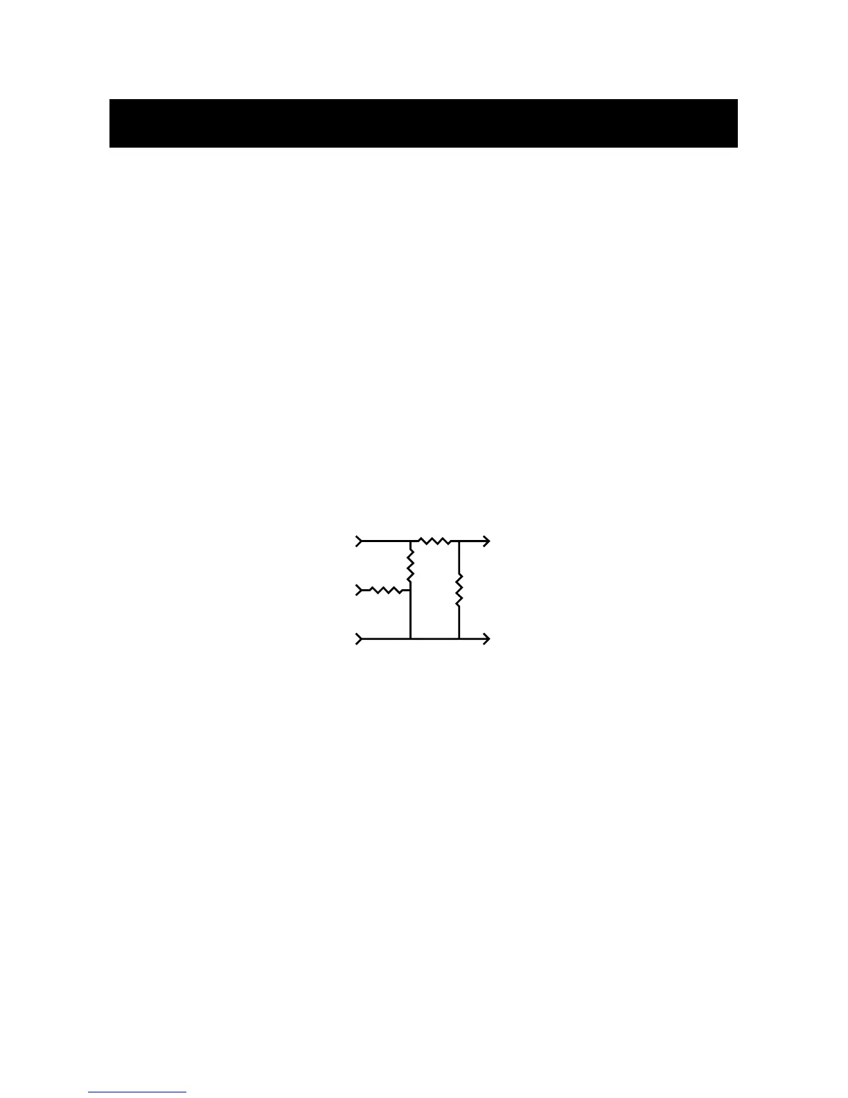
To get the most reliable interface, the noise immunity of the electrical interface should be
maximized. Drive level and impedance is higher with the AES/EBU interface, so the best
solution is to use a resistor network as shown below to match both parameters.
On some equipment, an SPDIF input processes 16 bits, on other 20 or 24 bits. When
driving SPDIF inputs, you should know how much data is being looked at, and set the 02R
output dither accordingly.
SPDIF output to UNIT•Y input.
Unless your SPDIF transmitter uses the 4 aux data bits for something else than audio, the
problem from going SPDIF to AES/EBU is typically electrical.
The best solution is to use an active balanced digital line driver close to the SPDIF output,
and 110 ohm cable onwards, but for short term setups, you may get by more easily:
A 75 ohm cable with a RCA phono type of connector in one end directly to the UNIT•Y
input. Because of the low level and unbalanced output signal, the cable should be kept
short (less than around 5 meter). At the UNIT•Y input, cold is connected to common.