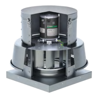
IM-4055
Installation, Operation & Maintenance Manual
12
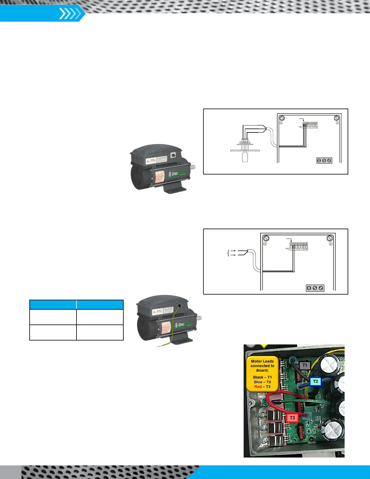
2. Connect the motor to the appropriate speed control option. The motor can accommodate 1 of 2 methods for speed control.
Connect the Speed Control Potentiometer to the motor control
as follows:
(Analog Input)
Use only Copper Wire for all wiring.
Connect the Control Signal Harness to the motor control as
follows:
Use only Copper Wire for all wiring.
It is the responsibility of the installer/controls engineer to ensure that any eld
supplied controls are compatible and functional with this motor technology. TCF
is not responsible for eld supplied or customer designed fan or motor controls.
3. Verify rotation of motor is correct by energizing the motor and checking that the
rotation matches the fan rotation label. This can also be done before any speed
controls are wired in by placing a jumper wire between terminals Pin 1 and Pin 2.
This will send 10 volts into the motor and cause it to run at full speed. To change
the rotation of the motor, swap the T1 (Black) and T2 (Blue) leads (as shown on
the right). Note that the motor and fan warranty are void if the motor is rotating
in the incorrect direction. Also verify that the motor speed control is functioning
properly.
Figure 6. Motor Speed Controlled by a Remote Speed
Control Dial (Potentiometer)
P10--1
Remote Speed
ControlDial
12VDC
AnalogIn
DGND
P10
Pin1= 12VDC
Pin2=AnalogIn
Pin3=DGND
Tighten to
5--7 lb-- in
L2 L1 N
Figure 7. Motor Speed Controlled by 0-10V DC
Control Signal
P10--1
P10
Pin2= AnalogIn
Pin3= DGND
Analog Input
0--10VDC
DGND
Tightento
5--7 lb-- in
L2 L1 N
Speed Control Options: TEFC Motors (cont.)
Descripon Wire Color
0-10V DC
(Analog Input)
Red
Ground
(DGND)
White
 Loading...