Installation, Operation & Maintenance Manual
IM-4055
5
Electrical Connection
standard).
2. The motor is factory set at the voltage marked on the fan
nameplate. Check the line voltage with the nameplate voltage.
3. The main power wiring should be sized for the ampacity
shown on the nameplate. Size wires in accordance with the
ampacity tables in Article 310 of the National Electrical Code.
4. Disconnect switches are not fused. The power leads must be protected at the point of distribution in accordance with the fan
nameplate.
5. All units must be electrically grounded in accordance with local codes or, in the absence of local codes, with the latest edition
conductor.
1. Use copper conductors only.
2. Protect wiring from sharp edges. Leave some slack in the
line to prevent damage. Do not allow the power or speed
control cables to kink or come in contact with oil, grease,
hot surfaces or chemicals. If damaged, discontinue use
immediately and have cord replaced. Use proper strain
relief.
CAUTION
Speed Control Options: ODP & TENV Motors
The following speed control options are
available for the Twin City Fan EC motor.
Coming standard with the motor is both a
motor mounted dial, for speed adjustment
supplied or supplied by TCF. See table to
the right for available control methods and
RPM for fan/motor combinations.
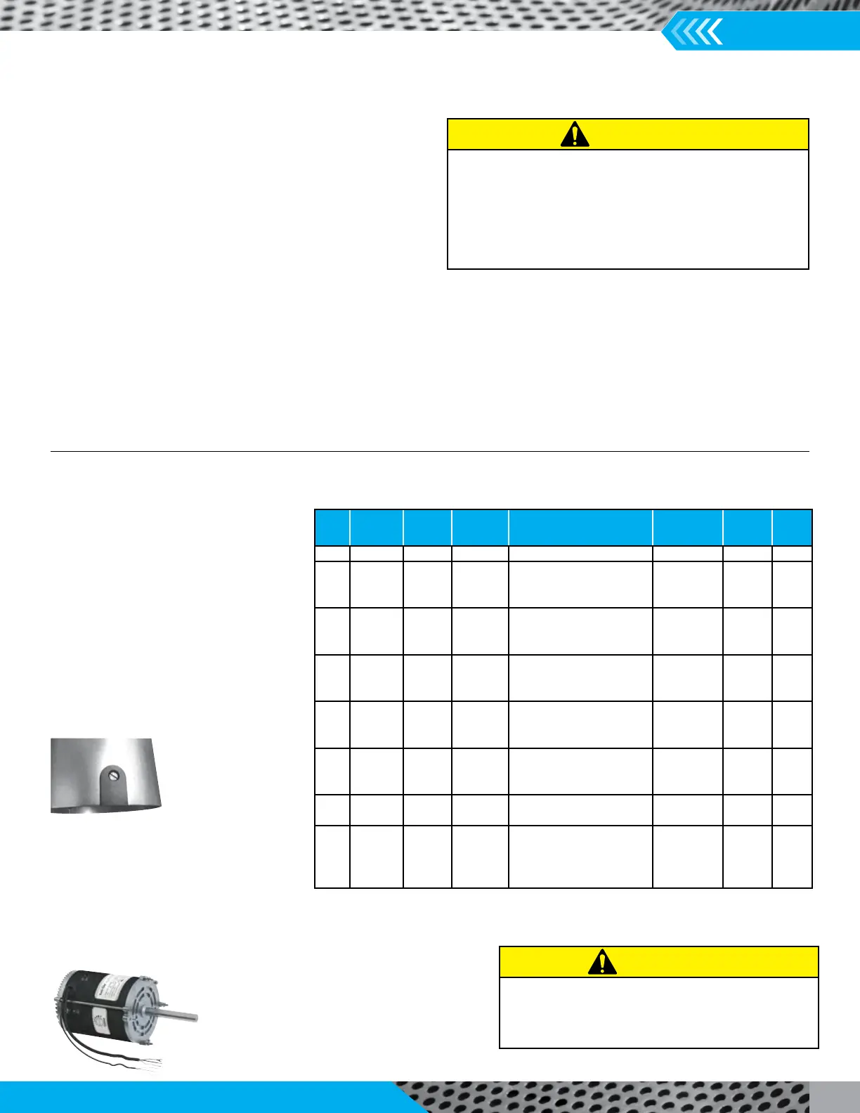
1. Motor Mounted
Dial, MMD (Standard
Feature)
– A potentiometer
is mounted to the
motor housing
control range. Speed adjustment is made
2. 0-10V DC Lead (Standard Feature)
signal and can be wired into building control
option, the control leads are terminated in a
HP Voltage Encl.
RPM
Range
Control Method
Motor
Part Nmbrs.
Opons Page
1/6 115 ODP 300-1800 MMD/0-10V/RMD 67001008 1,2,4 5-7
1/4 115 ODP 300-1800 MMD/0-10V/RMD 67001001 1,2,4 5-7
1/4 208-230 TENV 300-1800 MMD/0-10V/RMD 67002101 1,2,4 5-7
1/4 115-230 ODP 200-1800 GridPoint/0-10V/RMD 67001701 2,3,4 5-7
1/2 115 ODP 300-1800 MMD/0-10V/RMD 67001003 1,2,4 5-7
1/2 208-230 ODP 350-1800 MMD/0-10V/RMD 67001103 1,2,4 5-7
1/2 115/230 ODP 200-1800 GridPoint/0-10V/RMD 67001703 2,3,4 5-7
3/4 115 ODP 300-1800 MMD/0-10V/RMD 67001004 1,2,4 5-7
3/4 208-230 ODP 350-1800 MMD/0-10V/RMD 67001104 1,2,4 5-7
3/4 115/230 ODP 200-1800 GridPoint/0-10V/RMD 67001704 2,3,4 5-7
1 115 ODP 300-1800 MMD/0-10V/RMD 67001005 1,2,4 5-7
1 208-230 ODP 350-1800 MMD/0-10V/RMD 67001015 1,2,4 5-7
1 115/230 ODP 200-1800 GridPoint/0-10V/RMD 67001705 2,3,4 5-7
1 115 ODP 350-1200 MMD/0-10V/RMD 67001105 1,2,4 5-7
1 208-230 ODP 350-1200 MMD/0-10V/RMD 67001115 1,2,4 5-7
1 115/230 ODP 350-1200 GridPoint/0-10V/RMD 67001715 2,3,4 5-7
1 115 TEFC 200-1800 MMD/0-10V 67002205 Fig. 6, 7 12
2 208-230 TEFC 200-1800 MMD/0-10V 67002107 Fig. 6, 7 12
1 460 OPEN 300-1800 0-10V 67003405 Fig. 9 13
1-1/2 460 OPEN 300-1800 0-10V 67003406 Fig. 9 13
2 460 OPEN 300-1800 0-10V 67003407 Fig. 9 13
3 460 OPEN 300-1800 0-10V 67003409 Fig. 9 13
Always disconnect power before inspection or
maintenance. Although motor may be o and not
running when a 0-1.9V DC signal is present, high voltage
will still be present at the motor.
CAUTION
 Loading...