Installation, Operation & Maintenance Manual
IM-4055
11
Speed Control Options: TEFC Motors
This section covers the motors listed in the chart on the right.
Installation
Follow Figures 4 and 5 below for appropriate voltage. Use appropriate
strain relief (not provided) and branch protection.
AC power
Connect it to the motor control as follows:
a. Connect 115VAC (Black) to L1.
b. Connect Neutral (White) to N.
c. Connect Ground to
AC power
Connect it to the motor control as follows:
a. Connect 230V (White) to L1.
b. Connect 230V (Black) to L2.
c. Connect Ground to
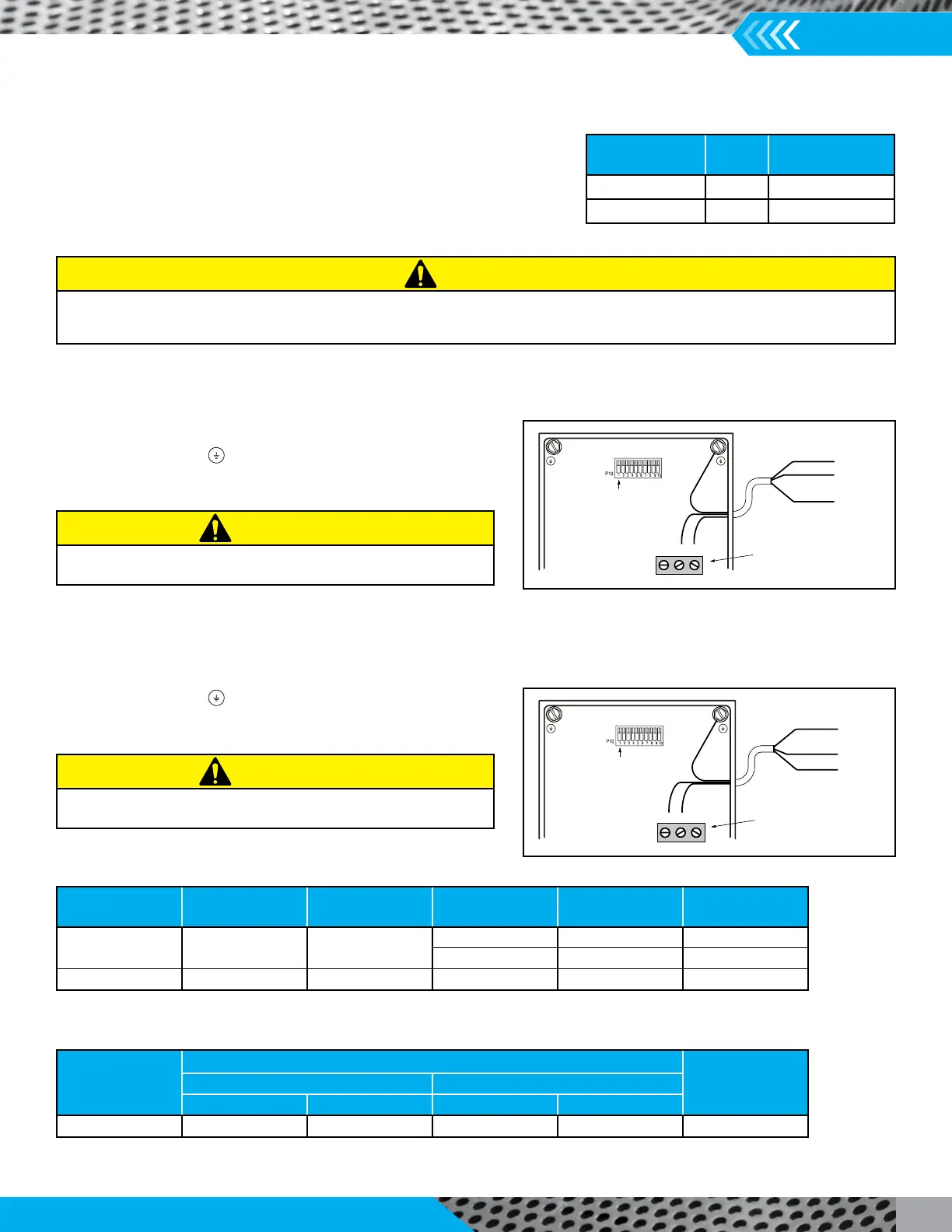
Figure 4. 115VAC Power Connection to Motor Speed
Controller
Green
White
115VAC Input Power
White
Green
Black
Black
P10
pin1
14 AWG
Tighten to 5--7 in-- lb
L2 L1 N
Figure 5. 230VAC Power Connection to Motor Speed
Controller
Green
White
230VAC Input Power
White
Green
Black
Black
P10
pin1
14 AWG
Tighten to 5--7 in-- lb
L2 L1 N
Table 1. Single Phase Power Requirements
Note:
Table 2. Branch Protection
Note: A different fuse Class may be used as an alternative to the Class shown, provided it is of the same or lesser
Motor
Part Numbers
HP Voltage/Phase
67002205 1 115/208-230/1
67002107 2 208-230/1
Do not remove conduit box cover for at least ve (5) minutes after AC power is disconnected to allow capacitors to discharge. Dangerous
voltages are present inside the equipment even when the motor is not rotating. Electrical shock can cause serious or fatal injury.
CAUTION
Connection of 115VAC power to “N” will damage the unit.
CAUTION
Connection of 230VAC power to “N” will damage the unit.
CAUTION
Nominal
AC Voltage
Minimum
AC Volts
Maximum
AC Volts
HP Input ARMS
Output
ARMS
115 103 126
1.0 12.0 2.83
1.0 6.0 2.83
230 200 264 2.0 12.0 5.29
Motor
Assembly
Fuses
Maximum
UL Listed
Circuit Breaker
Fast-Acng Time-Delay
Class Max Rang Class Max Rang
All (1HP-2HP) RK1 20A RK5 20A 20A