2800 LAURA LANE
l MIDDLETON, WI 53562 l (800) 288-9383 l FAX (608) 836-9044 l www.tcs-basys.com
11
9. Press the warmer button until the cooling setpoint is greater
than the current temperature by one degree. The cooling
stage(s) will sequence off. The fan will turn off 2 minutes
after the last cooling stage.
10. Go back to programming step #14 and set the setpoint
adjust limit back to the desired value. Make any other
changes in programming, clock, and schedule. Set the fan
and system modes to their desired settings.
11. If using remote sensors, verify that the reading is correct.
If not, see Wrong Temperature Display in the
Troubleshooting section.
TROUBLESHOOTING
No Display
Check for 24 VAC on terminals “+24” and “-24”. Check rib-
bon cable connecting the cover to the base for a good connec-
tion.
Fan Does Not Come On
The fan is on whenever the fan LED is on. If the fan should
be on, but the fan LED is off, check the fan (FAN SWITCH
button) and system modes (SYSTEM SWITCH button), and
the unoccupied fan mode in programming. If the fan is off but
the fan LED is on, check wiring. Short terminals “R” to “G”
and see if the fan comes on. This is a check for a mechanical
relay failure.
Heating or Cooling Does Not Come On
At least one stage of heating is on whenever the heating LED
is on, and at least one stage of cooling is on whenever the
cooling LED is on. If heating or cooling should be on but the
heating or cooling LED is off:
1. Check the fan and system switch modes.
2. Check the heating and cooling setpoints.
3. Check the room temperature to be sure heating or cooling
should be on.
4. Check the offsets and differentials.
5. If using outdoor air or discharge air high and low limits,
check their values to be sure heating or cooling is allowed.
If heating or cooling is off, but the corresponding SED is on,
check the wiring. Short terminals “R” to “W1”, “W2”
“Y1”,Y2”, or “B/O” and see if the heating or cooling comes
on. This is a check for a mechanical relay failure.
Wrong Temperature Display
If any of the temperatures is reading slightly high or low, there
are three adjustment pots located in the cover to adjust them.
“T1” is for the room temperature, “T2” is for the discharge air
temperature, and “T3” is for the outdoor air temperature. If
the temperature is at a minimum or maximum reading, check
the sensor dipswitch positions. (See setup instructions.)
Check for wiring problems (opens or shorts). A remote 1000
Ω sensor should read 1080 to 1090 Ω at room temperature.
The built-in sensor should read 108 to 109 Ω at room temper-
ature.
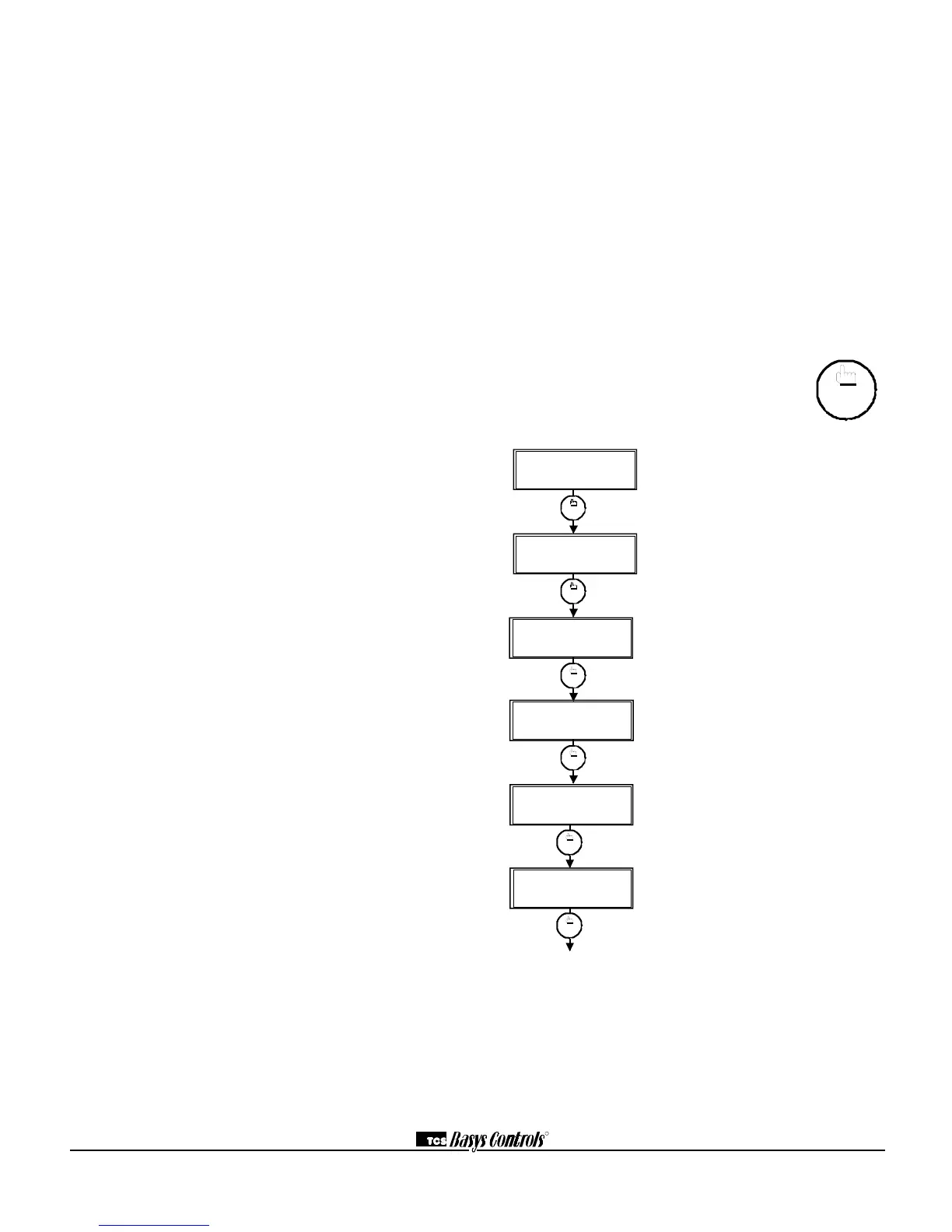
Override Status Screen. Shows whether
the override is active and if so, how many
minutes remaining.
Heat Stages Status Screen. Shows the
status of the first and second stages of
heating.
Service LED is On
If the service LED is on, it may be for monitoring purposes or
it may indicate a critical problem. The first monitoring
screen, which is used to indicate why the light is on, can be
accessed by pressing the SERVICE STATUS button.
Outputs Will Not Shut Off
First check room temperature and setpoints to determine
whether the output should be on. There are delays and mini-
mum on and off times for the fan and heating and cooling
stages. Also, check the service status menus to verify that the
outputs are on. Turning the system to “off” will instantly turn
all outputs off. The thermostat can be reset by pressing the
system switch button and the service status button simultane-
ously.
SERVICE SCREENS
Through repeated pressing of the SERVICE
STATUS button, the service screens (shown
below) are displayed, which enables you to moni-
tor various functions of the Superstat.
 Loading...