POWERING THE SUPERSTAT
Superstats are powered from 24 VAC +/- 20%.
If wiring for communications, dedicated power must be used
to power the Superstat. Several “S” Series thermostats may be
powered from the same transformer, provided that the trans-
former has sufficient power. (Superstats require 8 VA @ 24
VAC.)
Caution: Do not connect to 120 VAC. When mul-
tiple TCS/Basys Controls devices are using a single
transformer, the polarity of the power wiring must
be maintained because all TCS devices are half-
wave rectified and have common return paths.
When the Superstat is used as a stand-alone thermostat with-
out communications, the unit transformer may be used to
power it. To do this, install a jumper between the “R” and
“+24” terminals. The “24-” terminal must then be connected
to the common side of the unit transformer.
2800 LAURA LANE
l MIDDLETON, WI 53562 l (800) 288-9383 l FAX (608) 836-9044 l www.tcs-basys.com
2
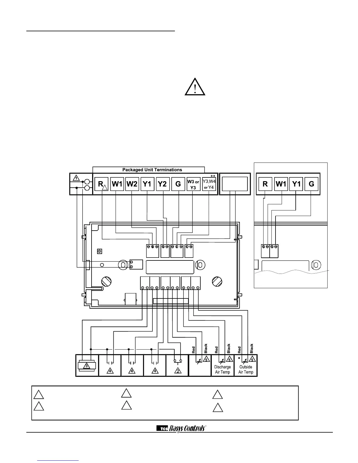
Wiring
The SZ1009, SZ1022, SZ1031 and SZ1035 use standard ter-
minal designations for wiring. See diagram below.
REMOTE TEMPERATURE SENSOR WIRING
Use 18 AWG shielded twisted-pair grounded at the sensor
mounting location. Sensor wiring runs of up to 250 feet are
attainable if properly shielded wire is used and the installation
environment is free of electrical noise. Sensor wire should be
kept at least five feet away from line voltage wiring.
The SZ1022 accepts two 2-wire remote sensors and the
SZ1009, SZ1031 and SZ1035 accept three. Consult the TS
Series Temperature Sensor Submittal Data Sheet for a com-
plete listing of packaging and application styles. When using
TCS/Basys Controls three-wire sensors, use the black and red
leads and either clip or twist off the white lead. Make sure that
the dip switches are set for the sensors you are using.
1
For communication wiring, use twisted,
shielded 18 AWG. Must be run
separately.
2
Dry momentary contact. Must not be
powered.
3
24 VAC transformer.
See powering instructions .
4
Dry contact. Must not be powered.
5
Sensor input wiring 18 AWG,
twisted, shielded pair.
*
Not available with the SZ1022.
6
Up to nominal 28 VAC from equipment
transformer.
A
B
Time Clock
Output
Remote
Zone/Return
Air Temp
R W1 W2
Y1 Y2
Y/W3
0 B/0 Y/W4 A2 A1
D13 0VR T1 T1+24 – DI1 DI2
A B
T2 T2 T3 T3
6
**
Available only on SZ1035. For 3 Heat &
3 Cool mode, B/O is W3 and Y/W4 is Y3.
R Y1 W1 G
A B
SZ1009 Output Wiring
See drawing at left for
input and power wiring.