SZ1009/SZ1022/
SZ1031/SZ1035
Conventional Heating &
Cooling Thermostats
Product Manual
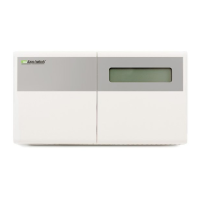
Description
The SZ1009, SZ1022, SZ1031 and SZ1035 are microproces-
sor-based programmable thermostats designed for conventional
heating and cooling applications. The SZ1009, and SZ1022
feature a 7-day time clock, while the SZ1031 and SZ1035 fea-
ture a 365-day time clock.
Features
z Stand-alone or network operation
z Adjustable delay on powerup for soft starts
z P+I control option
z Smart Recovery
z No battery backup required
z Built-in HVAC equipment protection
z 32 character LCD display
z 6 status LEDs
z Remote room sensing capability
z User setpoint adjustment limits
z Local and remote override capability
z System and fan switching with access lockouts
z Auxiliary time clock output (economizers)
z Equipment monitoring inputs and indication
z External time clock input
z Access to programming or schedule may be locked out or
limited with the use of an access code
z Fahrenheit or Celsius temperature display
Contents
Description . . . . . . . . . . . . . . . . . . . . . . . . . . . . . . . . . . . .1
Features . . . . . . . . . . . . . . . . . . . . . . . . . . . . . . . . . . . . . . .1
Mounting . . . . . . . . . . . . . . . . . . . . . . . . . . . . . . . . . . . . . .1
Wiring . . . . . . . . . . . . . . . . . . . . . . . . . . . . . . . . . . . . . . . .2
Setup . . . . . . . . . . . . . . . . . . . . . . . . . . . . . . . . . . . . . . . . .3
Programming . . . . . . . . . . . . . . . . . . . . . . . . . . . . . . . . . . .4
Setting Clock & Schedule . . . . . . . . . . . . . . . . . . . . . . . . .7
Program Options & Operating Features . . . . . . . . . . . . . . .8
Checkout & Troubleshooting . . . . . . . . . . . . . . . . . . . . . . .10
LED Description . . . . . . . . . . . . . . . . . . . . . . . . . . . . . . . .12
User’s Guide . . . . . . . . . . . . . . . . . . . . . . . . . . . . . . . . . . .12
Mounting
The SZ1009, SZ1022, SZ1031 and SZ1035 are designed for
wall mounting using two #6 sheet metal screws, either over a
horizontally installed 2” x 4” junction box, or directly to block
or drywall.
For best results, the thermostat should be mounted on an inte-
rior wall which reflects normal room environment, at a height
of approximately five feet from the floor. Avoid areas
exposed to direct sunlight, unusual heat sources, open doors
and windows, or unventilated locations.
If using a remote room sensor, it should be mounted in the
manner described above. The thermostat may then be mount-
ed in an area which is accessible for adjusting its settings.
Caution: Remove power from thermostat prior to
mounting.