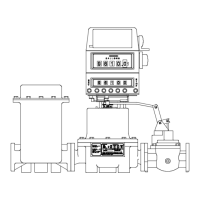
682 METER BODY REPAIR INSTRUCTIONS
I.
A. Remove all parts and seals from the meter body and clean them. You may air blast parts with
a glass bead material to clean parts.
B. Always replace bracket (#56), screws (#54) & (#34), plunger cups (#38) and Rulon seals
(#14, 17 & 44).
C. Check for:
1. Excessive wear on the wobble plate (#47) guide holes.
2. Pitting on ball bearings (#49) & (#46).
3. Excessive wear on the guide posts on main pivot bracket assembly (#53).
4. Wear on the AF/SP valve (#57) or SS valve insert (#57).
5. Wear on the valve seat (#58).
6. Wrinkles on the sleeves in cylinders (TCS 1-126891) of the body.
NOTE: Honing sleeves with Emory wheel may buff out wrinkles.
II.
A. Mount valve seat (#58) to body (#60), with seat gasket (#59).
B. Lap valve (#57) for AF, SP or SS.
1. AF & SP – Use Rectorseal® Clover lapping compound or equivalent on
valve (#57) & seat (#58). Move valve repeatedly in a Figure 8, and clean
compound off valve and seat thoroughly when finished.
2. SS – Use 220 & 320 grit silicon sand paper to lap valve & insert (#57).
Move valve repeatedly in a Figure 8 on 220 grit paper, then use the 320 grit
paper. Wipe valve Rulon insert clean.
C. Replace plunger cups (#38) in piston (#40) and carefully place into cylinders.
SEE PLUNGER CUP KIT for piston repair instructions. DO NOT cut or crimp plunger
cups.
D. Main Pivot & Wobble Plate Assembly.
1. Screw the main pivot assembly (#50) all the way into main pivot bracket
assembly (#53) and place pinion (#51) in its slot. For AF & SP meters,
unscrew the pinion and main pivot bracket assembly 5 full turns. For SS
meters, unscrew the pinion and main pivot bracket assembly 3 ½ full turns.
This should help bring meter within range while calibrating.
2. Drop the slotted screws (#54) into bracket.
3. Place bracket with screws into main pivot bracket assembly.
4. Set 5/8” ball bearing (#49) into position.
5. Place the wear plate (#48) over the screws (#54).
6. Set wobble plate (#47) onto the screws (#54) and fasten down with lock
nuts (#41) & lock washers (#42).
7. Set slack spring assembly (#45) on wobble plate post with Rulon washer
(#44) & slack roller (#43).
8. Mount main pivot bracket assembly to valve (#57) & seat (#58) with lock
washers (#42) & screws (#52).
E. Connect Pistons to Wobble Plate.
1. Carefully slide connector (#36) over the wobble plate (#47) bearing seats.
2. Place 1/2” ball bearing (#46) onto wobble plate and cover with bearing seat
(#35) & retainer (#33).
3. Rotate wobble plate (#47) & pistons (#40) through each cylinder to make
sure of smooth flowing characteristics.
 Loading...