47
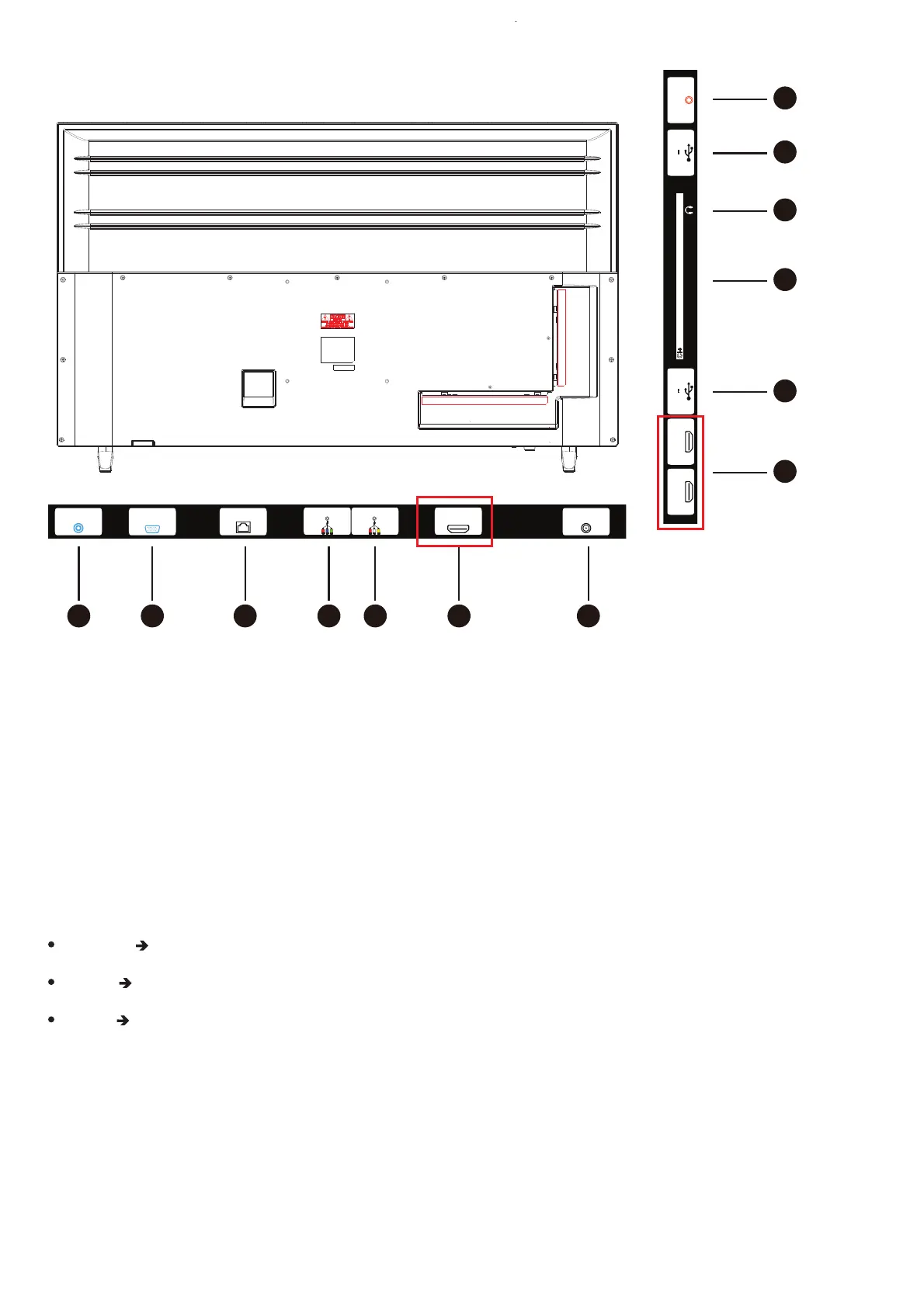
INPUTS
PC AUDIO VGA RJ45 YPbPr(mini) AV(mini) HDMI1 ANTENA
CI+
AuricularesHDMI2
(ARC)
HDMI3 USB
5Vdc 0.5A
S.SONIDO
DIGITAL
USB
5Vdc 0.5A
1 2 3 4 5 6 7
6
8
9
10
8
11
1.
PC AUDIO IN: 3.5 mm jack connector, to enter the tv the sound from a
device connected to VGA port.
Green Y Luma+sync
Blue Pb Difference of signal between BLUE and Luma
Red Pr Difference of signal between RED and Luma
2.
VGA: Common VGA e video connector is an "E" size D-sub connector,
with 15 pins in three rows, useful to connect external desktop or laptop. The
sound must be sent separately to the tv through the PC AUDIO IN port.
3.
RJ45: RJ45 Ethernet port. This port is compliant 10/100 mbs
4.
YPbPr mini: This is an input port to tv, to connect any device using the
normal three component video signal. The colour of connectors are as follows:
In the event you need to use this port, you must have the appropriate cable
male – to – male RCA Y PbPr, and connect to the female RCA adaptor. The
sound from this device must be input through the RED and WHITE of the AV
mini input port of the tv.