1-28 System 3
RZ5P Fiber Photometry Processor
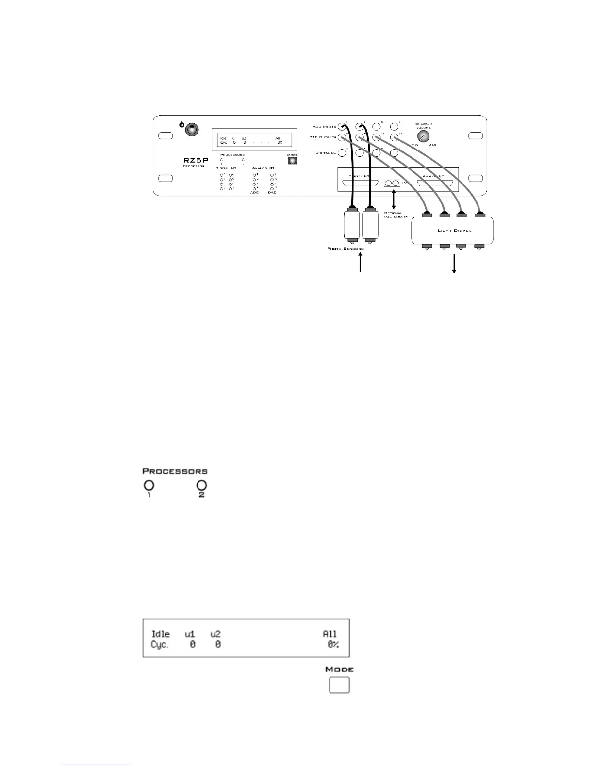
FiberPhotometryConnections
On the front panel of the RZ5P, connect photo sensors to ADC BNCs 1 and 2 and
connect light drivers to DAC BNCs 9 - 12.
FiberPhotometrySys t em ConnectionDiagram
The Analog I/O DB25 connector can also be used for the connections. See “DB25
Analog I/O Pinout” on page 1-32.
RZ5PFeatures
DSPStatusDisplays
The RZ5P include status lights and a VFD (Vacuum Fluorescent Display) screen to
report the status of the individual processors.
StatusLights
Two LEDs report the status of the multiprocessor's individual DSPs and will be lit
solid green when the corresponding DSP is installed and running. The corresponding
LED will be lit dim green if the cycle usage on a DSP is 0%. If the demands on
a DSP exceed 99% of its capacity on any given cycle, the corresponding LED will
flash red (~1 time per second).
FrontPanelVFDScreen