7-34 System 3
MS4/MS16 Stimulus Isolator
The final analog current output from the isolator is adjusted to match the stimulation
control waveform by adjusting the isolator’s driving voltage according to Ohm’s law
where: V=IR. That is, the driving voltage is adjusted for the stimulation control
waveform level and the electrode impedance. In this way, the stimulation current
specified by the user will be constant regardless of electrode impedance, within
system limits.
The MicroStimulator System standard configuration is capable of delivering up to 100
μA of current simultaneously across up to 16 stimulating electrodes (impedance up to
1 Mohm). See “Working with the MS16 MilliAmp Mode ” on page 7-48, for
information if your stimulus isolator has been configured for MilliAmp mode.
TheStimulusIsolator
The stimulus isolator features either four or 16 D/A converters that can deliver
arbitrary waveforms of up to 10 kHz bandwidth. PCM D/As are used to ensure
sample delays of only 4-5 samples and square edges on pulse stimulation
waveforms.
Each of the device’s stimulation channels can be configured in one of three states:
Stimulate: Channels in stimulate mode pass current through the selected electrodes.
Reference: Channels in reference mode become part of the return path for the
current. All channels in Reference mode use the same return path to analog ground
on the stimulator. Note: Users can also use a dedicated global reference channel as
a current return path. In this mode all channels can be used for stimulation.
Open: The Open mode is the default mode for all channels. In the open mode,
the corresponding electrode channel is disconnected from output and internally
grounded to eliminate noise and crosstalk. On multichannel electrodes, these
electrodes might instead be connected to a recording preamp. In this mode a
channel can be used to acquire neural signals.
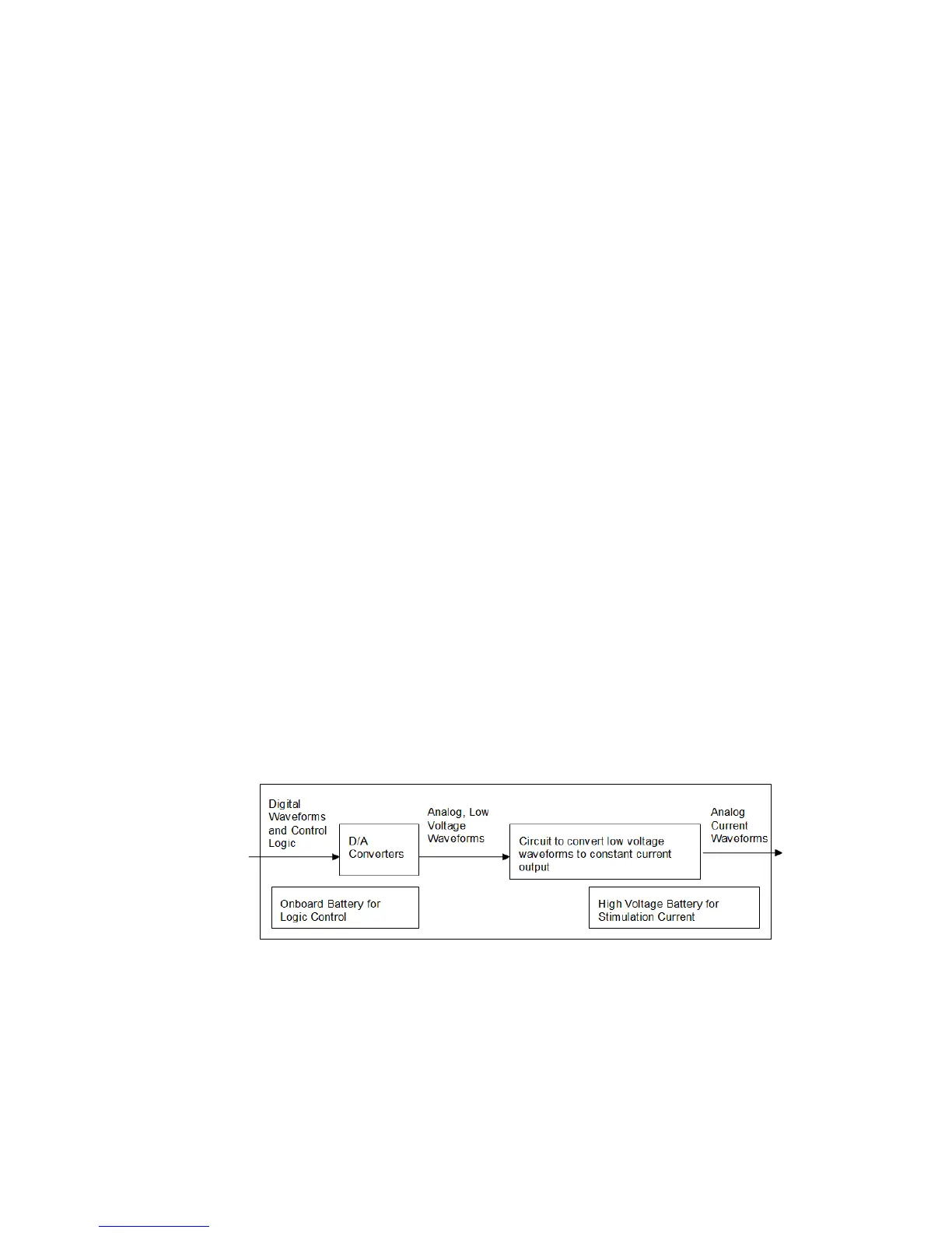
The stimulus isolator utilizes an onboard, rechargeable Li-Ion battery for logic control
and D/A converter operation. Special circuitry on the stimulus isolator draws on
external high voltage battery packs to convert low voltage waveforms from the D/A
converters to analog current waveforms as shown in the diagram below.
Stimulu sIsolatorDiagram
TheACC16ACCoupler
The stimulus isolator may generate a DC bias current of up to 0.2% of full scale
(up to 0.2 μA on 100 μA device) on any stimulation channel, even during a
quiescent state. While this may not have significant short-term effects, over time, it
may cause unintended tissue damage. This problem primarily affects researchers using
electrodes with impedance of more than 100 kOhms. Users may connect the ACC16