10-34 System 3
Acute (Non-ZIF) Headstages
TechnicalSpecifications
WARNING! When using multiple headstages ensure that all ground pins are
connected to a single common node. See “Headstage Connection Guide” on
page 6-93, for more information.
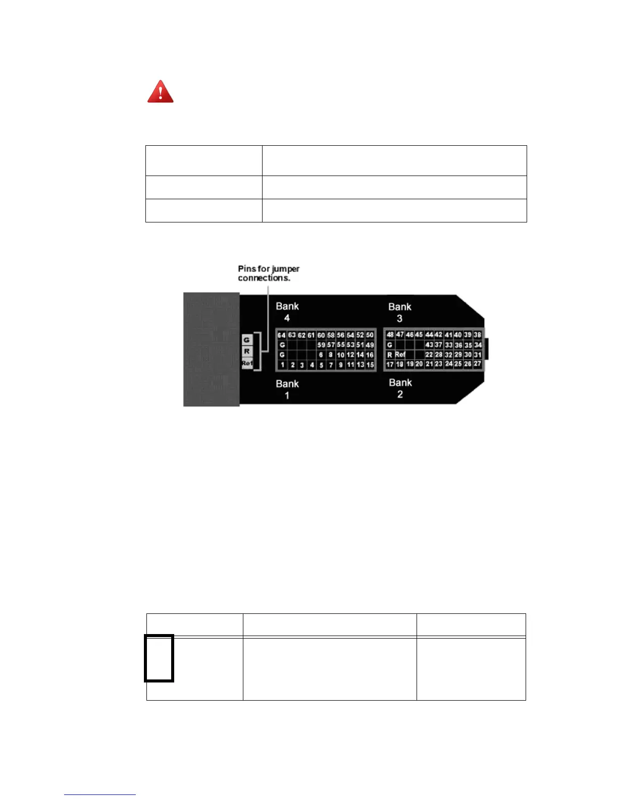
PinoutDiagram
(lookingintoconnections)
The numbers in the diagram above show the channel connections to the amplifier.
The headstage also features jumper locations to short G, R and Ref refers to the
built-in reference site on the NeuroNexus probe). The ground channel (G) should
either be tied to an external ground or to the reference (R) for a single ended
input.
Important! When using the NN64AC with the NeuroNexus Acute 64-channel probe, keep in
mind that there are several versions of the probe. Check the NeuroNexus Website for
pin diagrams. Also, see “MCMap” in the
RPvdsEx Manual
, for a description and
examples on how to re-map channel numbers.
JumperConfiguration
The following table describes the jumper configurations and associated requirements.
Input Referred Noise
rms 3 μV bandwidth 300-3000 Hz
rms 6 μV bandwidth 30-8000 Hz
Headstage Gain
Unity (1x)
Input Impedance
10
14
Ohms
Jumper Connections Operation Requirements
G
R
Ref
Shorts headstage Ground and Reference
inputs together, yielding single-ended
amplification of signals relative to
ground.
Connect common
Ground/Reference wire
to the headstage or
electrode.