17-26 System 3
BH32 Behavioral Cage Controller
Important! The two External Power Molex connectors on the top panel are shorted together; do
not use more than one external power source. The second external power connector
can be used to jumper the external power source to another BH32
VoltageModeToggle
This back panel switch toggles between 5 V and external power supply source for all
Molex output banks. Use 5 V mode for connections to mains power or PoE. Use
External Voltage mode for other external power sources up to 30 V.
PowerSwitch
The On/Off toggle switch turns the BH32 power off or on. The LED display will be
illuminated when the power is on.
StatusDisplay
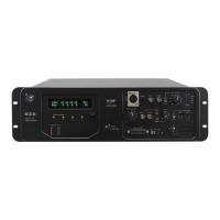
The front panel display screen reports system status. The Mode button to the left
toggles the display modes.
The display modes include:
1. Device Number - how the BH32 is recognized on the network by other
devices
2. Bank Status - bank direction and current state of all bits in each bank
3. NetBIOS name and IP address:
4. IP address of paired RZ device (if paired). See “RZ Configuration” on
page 17-30.
Push and hold the Mode button for two seconds then release to automatically cycle
through all of the display items, displaying each for one second.
Push and hold the Mode button for 10 seconds to reset the Device Number.
I/OControl
The BH32 is a net appliance that was designed to be used under a variety of
conditions, not all of which are available from vendors of behavioral control systems.
At the most basic the TDT BH32 system can replace existing devices such as the
Med Associates, Colburn or Lafayette systems that interface to a standard operant or
behavioral box with input and output lines, where the output lines drive feeders, lick
meters and other devices that require more than a digital trigger. At the more
complex level the TDT system can be used to send and receive complex signals to
control multiple hardware devices.
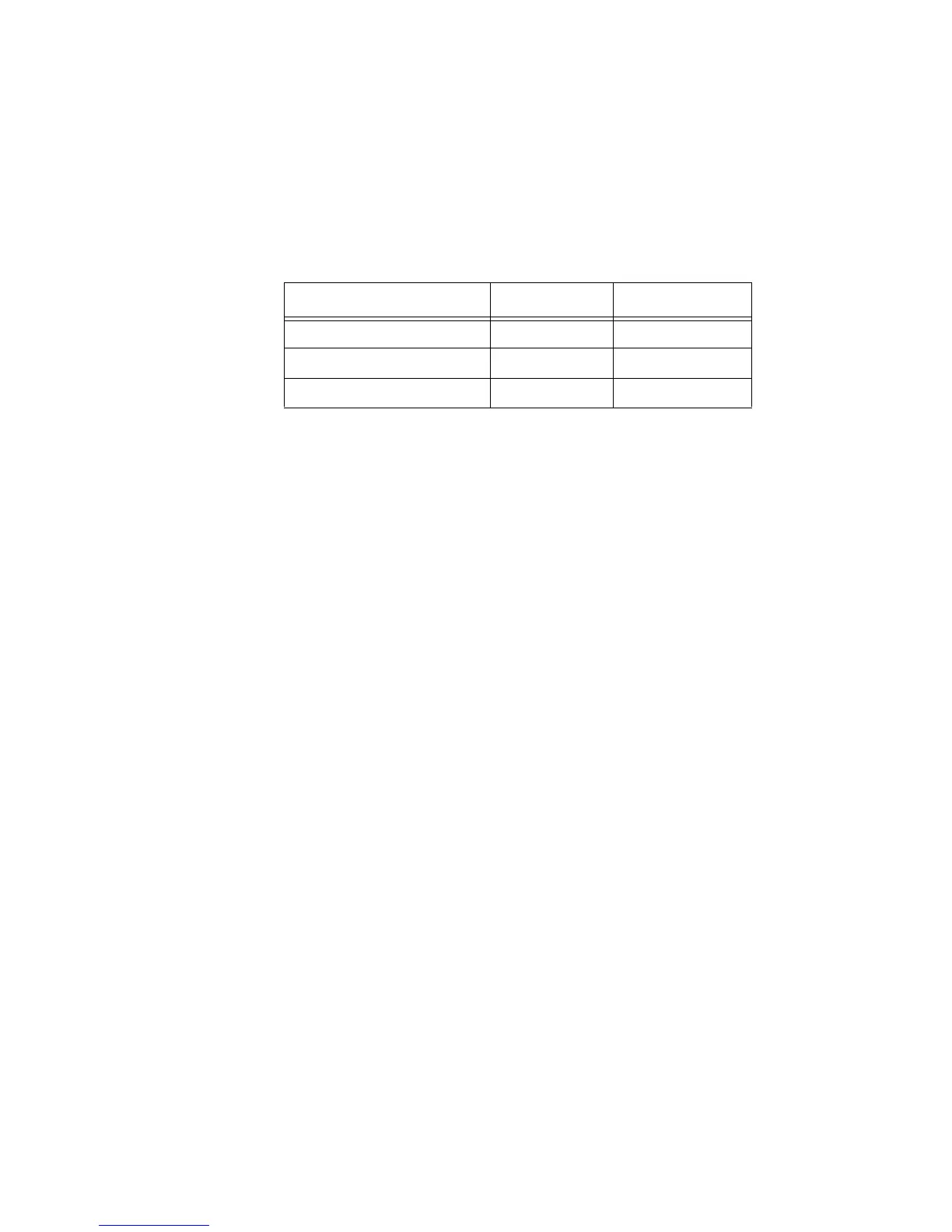
Power Source Mode Max Total Output
Mains power 5 V 200 mA
PoE 5 V 100 mA
External power up to 30 V External Voltage 3 A


 To Next Page