19-6 System 3
PO5/PO5e Optibit Interface
FO5StatusLEDs
Four status LEDs on the face of the FO5 indicate the connection status of the
interface.
Connected The Connected LED is lit when the interface is powered on and
the fiber optic cable labeled IN is connected properly. Although
the Connected LED will light if only the IN cable is connected,
both cables have to be connected properly for communication to
take place.
Identified The Identified LED lights when a software signal sent from the
PC is recognized by the interface. This takes place when
launching TDT software such as zBusMon, RPvdsEx or loading
an OpenEx project.
Activity The Activity LED is lit when data is being sent to or from the
TDT hardware.
Error The Error LED lights when there is a connection or
communication error. For example, this LED will light if the fiber
optic cables are not connected properly.
PO5/PO5eTechnicalSpecifications
Interface transfer rates vary by transfer type and device. See “Cycle Usage and
Large Transfers” on page 19-4, for more information.
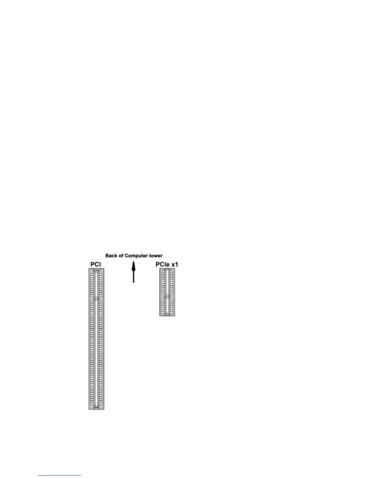
Below is a diagram of the compatible PCI and PCIe slots used with the PO5 and
PO5e Optibit Interface cards.
PO5e
The PO5e must be installed in a PCI Express
slot. The PO5e card uses a single lane (x1)
but may be used in any PCIe slot size (x1, x2,
x4, x8 or x16).
PO5
The PO5 zBus to PC interface card must be
installed in a standard size, compliant 3.3 V
slot. The PO5e zBus to PC interface card must
be installed in a PCI Express slot.
Notes:
Do not install in a PCI-X slot—the interface
might fail.
Do not attempt to install in low-profile PCI slots.
While low profile and standard PCI cards
maintain the same electricals, protocols, PC
signals, and software drivers as standard PCI
expansion cards, the low profile bracket is not
compatible with standard cards.
FiberOptics
Maximum cable length: 30 meters


 To Next Page