EasyManua.ls Logo

Teac A-X35 Service Manual

Teac A-X35
10 pages
To Next Page IconTo Next Page
Page #1 background imageLoading...
Page #1 background image
pn
eae
NOTES
in
this
manual,
0
dB
is
referenced
to
1V.
Ay
Parts
marked
with
this
sign
are
safety
critical
components.
They
must
always
be
replaced
with
\dentical
components
-
refer
to
the
appropriate
parts
list
and
ensure
exact
replacements.
PC
boards
shown
are
viewed
from
{oil
side.
Question and Answer IconNeed help?

Do you have a question about the Teac A-X35 and is the answer not in the manual?

Teac A-X35 Specifications

General IconGeneral
TypeIntegrated Amplifier
Frequency Response10Hz
Total Harmonic Distortion (THD)0.1%
Input Sensitivity150 mV (Line)
Input Impedance47kΩ (Line)
Speaker Load Impedance4 to 16 ohms

Summary

1 SPECIFICATIONS

2 ADJUSTMENT LOCATION

1-1 DC BALANCE CHECK

Checks DC voltage at speaker terminals for balance. Ensure within ±20mV.

1-2 IDLING CURRENT CHECK

Measures idling current at specific test points. Adjust if over 12mV.

3 VOLTAGE CONVERSION

4 BLOCK DIAGRAM

4 BLOCK DIAGRAM

Provides a high-level overview of the amplifier's functional blocks and signal flow.

5 IC BLOCK DIAGRAM

Illustrates the internal circuit of key integrated circuits used in the amplifier.

6 EXPLODED VIEW

7 SCHEMATIC DIAGRAM

8 EXPLODED VIEW PARTS LIST

9 PC BOARD AND PARTS LIST

9.1 MAIN AMP PCB CA-A505 (1L)

Details for the Main Amplifier PCB assembly CA-A505, including components.

TONE PCB T-A510

Lists components and details for the Tone PCB assembly T-A510.

POWER LED PCB

Lists components and details for the Power LED PCB.

9.2 FUNCTION LED PCB L-A513(L)

9.2 FUNCTION LED PCB L-A513(L)

Details for the Function LED PCB L-A513(L).

SWITCH PCB S-A517(A,L)

Details for the Switch PCB S-A517(A,L).
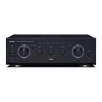
Related product manuals