AAGG--DD88990000
SERVICE MANUAL
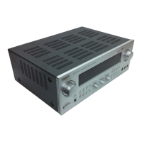
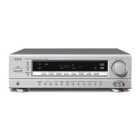
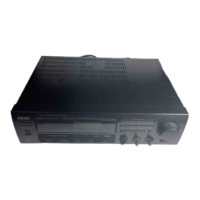
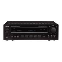
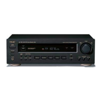
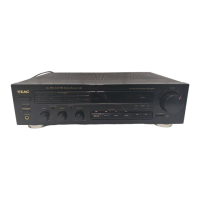
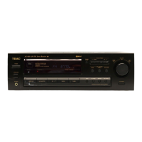
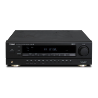
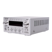
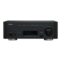
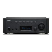
AV Digital Surround Receiver
Effective : January, 2002 S-0000A
CONTENTS
SAFETY INSTRUCTIONS ・・・・・・・・・・・・・・・・・・・・・・・・・・・・・・・・・2
SPECIFICATIONS
・・・・・・・・・・・・・・・・・・・・・・・・・・・・・・・・・・・・・・・・・3
MEASUREMENTS AND ADJUSTMENTS
・・・・・・・・・・・・・・・・5
FIP DISPLAY
・・・・・・・・・・・・・・・・・・・・・・・・・・・・・・・・・・・・・・・・・・・・・・・8
DISPLAY PIN CONNECTION
・・・・・・・・・・・・・・・・・・・・・・・・・・・・・9
IC BLOCK DIAGRAMS AND PIN FUNCTIONS
・・・・・・・・・10
EXPLODED VIEWS AND PARTS LIST
・・・・・・・・・・・・・・・・・・22
PC BOARDS AND PARTS LIST
・・・・・・・・・・・・・・・・・・・・・・・・・24
INCLUDED ACCESSORIES
・・・・・・・・・・・・・・・・・・・・・・・・・・・・・29
目次
SAFETYINSTRUCTIONS・・・・・・・・・・・・・・・・・・・・・・・・・・・・・・・・・・2
仕様
・・・・・・・・・・・・・・・・・・・・・・・・・・・・・・・・・・・・・・・・・・・・・・・・・・・・・・・・・4
測定と調整
・・・・・・・・・・・・・・・・・・・・・・・・・・・・・・・・・・・・・・・・・・・・・・・・・・5
FIPディスプレイ ・・・・・・・・・・・・・・・・・・・・・・・・・・・・・・・・・・・・・・・・・・・・・8
ディスプレイピン接続
・・・・・・・・・・・・・・・・・・・・・・・・・・・・・・・・・・・・・・・・9
ICブロック図とピン機能
・・・・・・・・・・・・・・・・・・・・・・・・・・・・・・・・・・・・ 10
分解図とパーツリスト ・・・・・・・・・・・・・・・・・・・・・・・・・・・・・・・・・・・・・・22
基板図とパーツリスト
・・・・・・・・・・・・・・・・・・・・・・・・・・・・・・・・・・・・・・24
付属品
・・・・・・・・・・・・・・・・・・・・・・・・・・・・・・・・・・・・・・・・・・・・・・・・・・・・・ 29
NOTES
●
PC boards shown are viewed from parts side.
●
The parts with no reference number or no parts number in the
exploded views are not supplied.
●
As regards the resistors and capacitors, refer to the circuit diagrams
contained in this manual.
●
£ Parts marked with this sign are safety critical components. They
must be replaced with identical components - refer to the appropriate
parts list and ensure exact replacement.
●
Parts of [ ] mark can be used only with the version designated.
[J]:JAPAN[US]:U.S.A.[C]:CANADA
注 意
●
プリント基板図は部品面を示しています。
●
分解図に部番のない部品および品番のない部品は供給できま
せん。
●
標準の抵抗、コンデンサーは省略してあります。
回路図を参照してください。
●
£印は安全重要部品です。
交換する時は必ず指定の部品を使用してください。
●
仕向先
[J]:JAPAN[US]:U.S.A.[C]:CANADA