

B
beverly93Aug 5, 2025
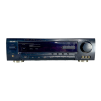
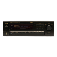
Why is my Teac AG-680 Stereo Receiver remote control not working?
- HhblackwellAug 5, 2025
The remote control might not be working because the batteries are exhausted. Replace them with new batteries. Alternatively, the remote control unit may be too far from the receiver or out of the effective range. Try operating the remote control unit within the effective range.