Do you have a question about the Teac AG-H300 and is the answer not in the manual?
Technical details for the Amplifier section, including power output and frequency response.
Technical details for the FM tuner section, including tuning range and sensitivity.
Technical details for the AM tuner section, including tuning range and sensitivity.
General operational specifications like power requirements and dimensions.
List of accessories included with the unit.
Instructions and required equipment for aligning the receiver's tuning circuits.
Diagram showing specific points for adjustments on the tuner board.
Procedure for adjusting the FM tuning frequency range using a DC voltmeter.
Procedure for adjusting the AM tracking for optimal signal reception.
Procedure for adjusting FM mono distortion using a distortion meter.
Procedure for adjusting FM/AM auto stop levels using signal generators.
Detailed descriptions of each pin function for the Micom BVITMP87PM78F IC.
An exploded view illustrating the physical arrangement of internal components.
A detailed list of parts with reference numbers and descriptions.
Part numbers and descriptions for components on the Main PCB.
Part numbers and descriptions for components on the Front PCB.
Part numbers and descriptions for components on the Tuner PCB.
List of included accessories with their part numbers and descriptions.
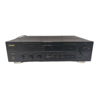
| Type | Stereo Receiver |
|---|---|
| Audio Channels | 2 |
| Frequency Response | 10 Hz - 100 kHz |
| Input Sensitivity | 200 mV |
| FM Tuning Range | 87.5 - 108 MHz |
| Input Impedance | 47 kΩ |
| Weight | 5 kg |
| Tuning range | FM, MW |
| Inputs | 1 x phono |
| Outputs | Headphones |
| Speaker Load Impedance | 8 ohms |