Do you have a question about the Teac CR-H100 and is the answer not in the manual?
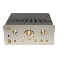
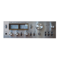
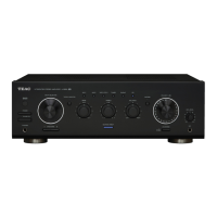
Details amplifier performance parameters like power output, distortion, S/N ratio, input sensitivity, and tone control.
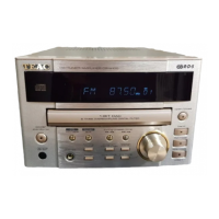
Covers FM tuning range, usable sensitivity, distortion, signal-to-noise ratio, and frequency response.
Outlines AM tuning range, sensitivity, selectivity, frequency response, and signal-to-noise ratio.
Specifies CD player performance metrics such as signal-to-noise ratio, THD, channel separation, balance, frequency response, and wow flutter.
Lists general specifications including power consumption, power requirements, dimensions, and weight.
Details the included accessories such as remote control unit, operator's manual, AM loop antenna, and FM antenna.
Describes voltage adjustments for FM and AM tracking, connecting to test points TP1 and GND.
Details RF adjustment for AM, connecting signal generator to AM ANT and adjusting for maximum sensitivity.
Outlines RF adjustment for FM, connecting signal generator to FM ANT JACK and adjusting for maximum sensitivity.
Explains FM mono distortion adjustment using DC voltmeter, signal generator, and distortion meter.
Details FM/AM auto stop level adjustment, connecting signal generators and adjusting specific VRs.
Provides a disassembly drawing and parts list for the KSL-2130CCM mechanism, view 1.
Presents a disassembly drawing and parts list for the KSL-2130CCM mechanism, view 2.
Explains the numbering system for resistors, including type, wattage, shape, tolerance, and value.
Details the numbering system for capacitors, covering type, voltage, value, tolerance, and peculiarity.