EasyManua.ls Logo

Teac BX-500 Service Manual

Teac BX-500
35 pages
To Next Page IconTo Next Page
Page #1 background imageLoading...
Page #1 background image
TEAC
SERVICE
MANUAL
BX-300
High
Speed
DC
Integrated
Amplifier
BX-300
DC
Integrated
Amplifier
CONTENTS
1.
Specifications
and
service
data...
2.2...
ee
ee
es
2
2.
Parts
WOCAtiON
=
650
oS
S0e
Be
aca
Se
ce
ee
a
ee
Stee
ap
ale
a
ae
eS
ee
eae
a
ee
3
3.
Adjustments
and
voltage
conversion...
2.2...
ee
ee
es
4
4.
Block
and
level
diagram
2...
ee
ee
ee
6
5.
Parts
location
and
parts
list
(BX-500)
2.2...
es
8
6.
Parts
location
and
parts
list
(BX-300)
..
2...
2.
ee
ee
ee
14
7.
PC
boards
and
parts
list
(BX-500).
2...
ee
ee
20
8.
PC
boards and
parts
list
(BX-300)..
2...
ee
ee
26
CAUTION
A.
Parts
marked
with
this
sign
are
safety
critical
components.
They
must
always
be
replaced
with
identical
components
-
refer
to
the
TEAC
Parts
List
and
ensure
exact
replacement.
Effective:
August,
1979
C-90019
5704001500
Question and Answer IconNeed help?

Do you have a question about the Teac BX-500 and is the answer not in the manual?

Teac BX-500 Specifications

General IconGeneral
TypeIntegrated Stereo Amplifier
Input Sensitivity2.5mV (MM), 150mV (line)
Output150mV (line)
Tone ControlsBass, Treble
Loudness ControlYes
Frequency Response10Hz to 50kHz
Total Harmonic Distortion0.05%
Signal-to-Noise Ratio76dB (MM), 90dB (line)
Speaker load impedance4Ω to 16Ω
InputsPhono MM, Tuner, AUX, Tape
OutputsTape1, Tape2
Power SupplyAC 120V, 60Hz

Summary

Specifications and Service Data

Parts Location

Parts Location Diagram 1

Diagram showing component locations on the front panel.

Adjustments and Voltage Conversion

Before Adjustment Procedures

Initial setup steps before performing adjustments.

Mid-Point Potential Adjustment

Adjusting the DC voltmeter reading to zero.

Idling Current Adjustment

Adjusting the amplifier's bias current.

Power Output Meter Adjustment (BX-500)

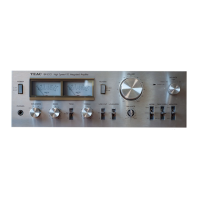
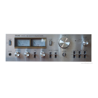
Calibrating the power output meters on the BX-500 model.

Voltage Conversion (General Export)

Instructions for changing voltage settings on export models.

Block and Level Diagrams

Parts Location and Parts List (BX-500)

BX-500 Parts Location Diagram 1

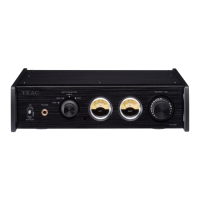
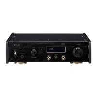
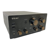
Component identification on the front panel for BX-500.

BX-500 Parts Location Diagram 2

Component identification on the rear panel for BX-500.

BX-500 Parts Location Diagram 3

Component identification on the internal chassis for BX-500.

BX-500 Parts Location Diagram 4

Component identification on internal PCBs for BX-500.

BX-500 Parts Location Diagram 5

Component identification on rear connectors for BX-500.

Parts Location and Parts List (BX-300)

BX-300 Parts Location Diagram 1

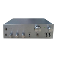
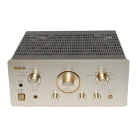
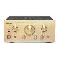
Component identification on the front panel for BX-300.

BX-300 Parts Location Diagram 2

Component identification on the rear panel for BX-300.

BX-300 Parts Location Diagram 3

Component identification on the internal chassis for BX-300.

BX-300 Parts Location Diagram 4

Component identification on internal PCBs for BX-300.

BX-300 Parts Location Diagram 5

Component identification on rear connectors for BX-300.

PC Boards and Parts List (BX-500)

BX-500 Main PCB Assembly

Component listing and diagram for the main PCB.

BX-500 Tone Control Amplifier PCB

Component listing and diagram for the tone control amp PCB.

BX-500 Switch PCB Assembly

Component listing and diagram for the switch PCB.

BX-500 Volume PCB Assembly

Component listing and diagram for the volume control PCB.

BX-500 Input/Output PCB Assembly

Component listing and diagram for the I/O PCB.

BX-500 Meter Amplifier PCB Assembly

Component listing and diagram for the meter amplifier PCB.

PC Boards and Parts List (BX-300)

BX-300 Main PCB Assembly

Component listing and diagram for the main PCB.

BX-300 Tone Control Amplifier PCB

Component listing and diagram for the tone control amp PCB.

BX-300 Switch PCB Assembly

Component listing and diagram for the switch PCB.

BX-300 Input/Output PCB Assembly

Component listing and diagram for the I/O PCB.

Included Accessories

Assembling Hardware Coding List

Schematic Diagrams

BX-300 Schematic Diagram

Electrical circuit diagram for the BX-300 amplifier.

BX-500 Schematic Diagram

Electrical circuit diagram for the BX-500 amplifier.

Related product manuals