Do you have a question about the Teac BX-330 and is the answer not in the manual?
Technical performance parameters and operational data.
Operational details and performance metrics.
Steps for adjusting the unit's voltage settings.
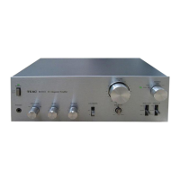
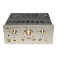
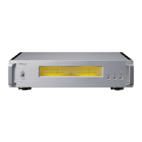
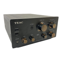
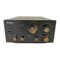
Visual guide to parts on the BX-550 unit.
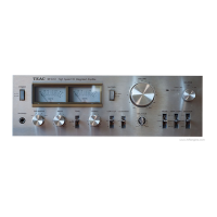
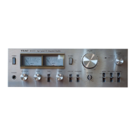
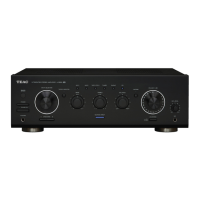
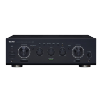
Visual guide to parts on the BX-330 unit.
Initial settings before performing calibration.
DC offset calibration procedure.
Setting bias current for amplifier stages.
Calibration of output level indicators.
Schematic showing signal path and levels for BX-550.
Schematic showing signal path and levels for BX-330.
Visual guide to front panel components.
Visual guide to internal and rear components.
Visual guide to front panel components.
Visual guide to internal and rear components.
Detailed component list for the main PCB.
Component lists for tone control and switch PCBs.
Component lists for muting, input/output, and meter PCBs.
Detailed component list for the main PCB.
Component lists for tone control and switch PCBs.
Component lists for input/output and LED PCBs.
Diagrams showing pin configurations for semiconductors.
Information on included user manuals.
Overall circuit schematic for the BX-330.
Overall circuit schematic for the BX-550.
| Type | Integrated Stereo Amplifier |
|---|---|
| Input Sensitivity | 2.5mV (MM), 150mV (line) |
| Frequency Response | 10Hz to 50kHz |
| Signal-to-Noise Ratio | 85dB (line) |
| Speaker Load Impedance | 8 ohms |