Do you have a question about the Teac BX-550 and is the answer not in the manual?
Detailed technical specifications for BX-550 and BX-330 models.
Key performance parameters and test points for servicing.
Instructions for safely changing the unit's voltage setting.
Visual guides identifying component locations on the BX-550.
Visual guides identifying component locations on the BX-330.
Initial settings required before performing calibration.
Adjusting DC voltage at amplifier mid-points for optimal performance.
Procedure for setting quiescent current in amplifier stages.
Calibrating the power output meter on the BX-550 model.
Calibrating the LED level meter on the BX-330 model.
Functional block diagram and signal flow for BX-550.
Functional block diagram and signal flow for BX-330.
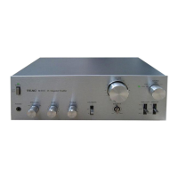
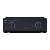
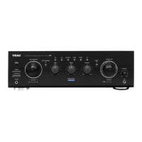
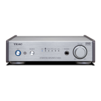
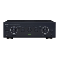
Visual guide for front panel component identification on BX-550.
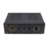
Visual guide for rear panel and internal component identification on BX-550.
Visual guide for internal component identification on BX-550.
Visual guide for internal component identification on BX-550.
Visual guide for rear panel component identification on BX-550.
Visual guide for internal component identification on BX-550.
Visual guide for internal component identification on BX-550.
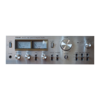
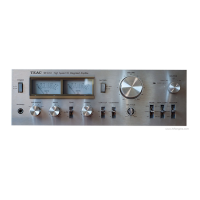
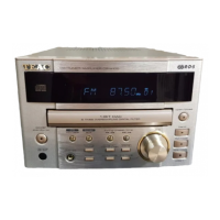
Visual guide for front panel component identification on BX-330.
Visual guide for internal component identification on BX-330.
Visual guide for internal component identification on BX-330.
Visual guide for internal component identification on BX-330.
Visual guide for internal component identification on BX-330.
Visual guide for internal component identification on BX-330.
Codes and types for screws, washers, and nuts used in assembly.
Component layout and parts for the BX-550 main board.
Component layout and parts for BX-550 tone control amplifier board.
Component layout and parts for BX-550 tone control amplifier board.
Component layout and parts for BX-550 switching PCB.
Component layout and parts for BX-550 meter amplifier board.
Component layout and parts for BX-550 muting switch PCB.
Component layout and parts for BX-550 input/output PCB.
Component layout and parts for the BX-330 main board.
Component layout and parts for BX-330 tone control amplifier board.
Component layout and parts for BX-330 switching PCB.
Component layout and parts for BX-330 LED display PCB.
Component layout and parts for BX-330 LED display PCB.
Component layout and parts for BX-330 LED display PCB.
Component layout and parts for BX-330 variable resistor PCB.
Visual representation of semiconductor pin configurations and connections.
List of included accessories such as manuals and cables.
Detailed circuit schematic for the BX-330 amplifier.
Detailed circuit schematic for the BX-550 amplifier.
| Input Sensitivity | 150mV (line) |
|---|---|
| Output | 150mV (line) |
| Speaker Load Impedance | 8Ω to 16Ω |
| Weight | 9.3 kg |
| Power Output | 50 W per channel into 8Ω (stereo) |
| Frequency Response | 5Hz to 60kHz |