Do you have a question about the Teac BX-300 and is the answer not in the manual?
Safety critical components must be replaced with identical ones.
Detailed technical specifications for BX-500 and BX-300 models.
Performance data and characteristics for BX-500 and BX-300 models.
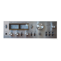
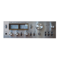
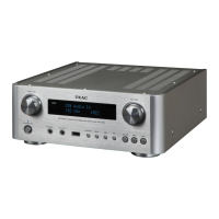
Visual identification of parts on the BX-500 front panel assembly.
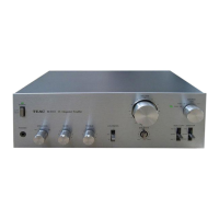
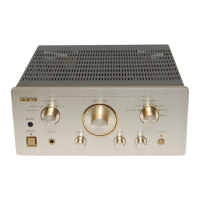
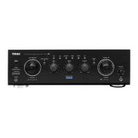
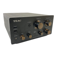
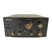
Visual identification of parts on the BX-300 front panel assembly.
Preparation steps before performing unit adjustments.
Procedure to adjust the mid-point potential using a DC voltmeter.
Steps to adjust the idling current using a DC voltmeter.
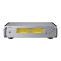
Procedure to adjust the power output meters on the BX-500.
Guide for converting voltage settings on export models.
Block diagram illustrating the signal flow for the BX-500.
Level diagram showing signal amplitudes at various stages for BX-500.
Block diagram illustrating the signal flow for the BX-300.
Level diagram showing signal amplitudes at various stages for BX-300.
Visual identification and reference numbers for BX-500 front panel parts.
Detailed list of parts with part numbers and descriptions for BX-500.
Visual identification and reference numbers for BX-500 rear/side panel parts.
Detailed list of parts with part numbers and descriptions for BX-500.
Visual identification and reference numbers for BX-500 internal components.
Visual identification and reference numbers for BX-500 internal components.
Detailed list of parts with part numbers and descriptions for BX-500.
Visual identification and reference numbers for BX-500 internal components.
Detailed list of parts with part numbers and descriptions for BX-500.
Visual identification and reference numbers for BX-500 rear panel connectors.
Detailed list of parts with part numbers and descriptions for BX-500.
Visual identification and reference numbers for BX-300 front panel parts.
Detailed list of parts with part numbers and descriptions for BX-300.
Visual identification and reference numbers for BX-300 rear/side panel parts.
Detailed list of parts with part numbers and descriptions for BX-300.
Visual identification and reference numbers for BX-300 internal components.
Visual identification and reference numbers for BX-300 internal components.
Detailed list of parts with part numbers and descriptions for BX-300.
Visual identification and reference numbers for BX-300 internal components.
Detailed list of parts with part numbers and descriptions for BX-300.
Visual identification and reference numbers for BX-300 rear panel connectors.
Detailed list of parts with part numbers and descriptions for BX-300.
Component layout and identification for the BX-500 main PCB.
Component layout and identification for the BX-500 Tone Control Amplifier PCB.
Component layout and identification for the BX-500 SW PCB.
Component layout and identification for the BX-500 Volume PCB.
Component layout and identification for the BX-500 In/Output PCB.
Component layout and identification for the BX-500 Meter Amplifier PCB.
Detailed component list for the BX-500 Main PCB.
Component list for the BX-500 Tone Control Amplifier PCB.
Component list for the BX-500 SW PCB.
Component list for the BX-500 In/Output PCB.
Component list for the BX-500 Volume PCB.
Component list for the BX-500 Meter Amplifier PCB.
Component layout and identification for the BX-300 main PCB.
Component layout and identification for the BX-300 Tone Control Amplifier PCB.
Component layout and identification for the BX-300 SW PCB.
Component layout and identification for the BX-300 In/Output PCB.
Detailed component list for the BX-300 Main PCB.
Component list for the BX-300 Tone Control Amplifier PCB.
Component list for the BX-300 SW PCB.
Component list for the BX-300 In/Output PCB.
Explanation of screw codes and types used in assembly.
Explanation of washer and nut codes and types used in assembly.
Schematic diagram for the BX-500 Main PCB.
Schematic diagram for the BX-500 In/Output PCB.
Schematic diagram for the BX-500 SW PCB.
Schematic diagram for the BX-500 Volume PCB.
Schematic diagram for the BX-500 Tone Control Amplifier PCB.
Schematic diagram for the BX-500 Meter Amplifier PCB.
Schematic diagram for the BX-300 Tone Control Amplifier PCB.
Schematic diagram for the BX-300 Main PCB.
Schematic diagram for the BX-300 LED PCB.