Do you have a question about the Teac X-300 and is the answer not in the manual?
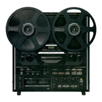
Device technical details: tape system, heads, reel size, speeds, inputs, outputs.
Mechanical parameters: tape speed deviation, wow/flutter, pinch roller pressure.
Measuring and adjusting brake torque for tape control.
Measuring and adjusting take-up and back tension torque for reel motors.
Adjusting tape speed to meet specified accuracy requirements.
Checking wow and flutter to ensure audio quality.
Aligning heads and tape path for optimal audio playback and recording.
Checking the power supply voltage for proper operation.
Checking playback performance characteristics.
Checking playback frequency response across different speeds.
Checking playback signal-to-noise ratio for audio clarity.
Checking recording performance characteristics.
Locating adjustment points and test points on PCBs.
Diagram and component list for REC/PLAY AMPL PCB.
Diagram and component list for Power Supply PCB.
Control circuit schematic diagram.
Schematic for the capstan motor servo PCB.
Amplifier circuit schematic diagram.
Schematic for the REC/PLAY AMPL PCB.
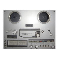
| Type | auto reverse, 3-head, 4-track stereo tape deck |
|---|---|
| Track System | 4-track, 2-channel stereo |
| Total Harmonic Distortion | 0.8% |
| Output | 0.3V (line) |
| Output Level | 0.3V |
| Heads | 1 x record, 1 x playback, 1 x erase |
| Motor | 2 |
| Tape Type | CrO2, Metal |
| Wow and Flutter | 0.04% (WRMS) |
| Noise Reduction | Dolby B, Dolby C |
| Power Supply | AC 120V |