12
TEC-61231-23 Technical Manualе PRIZRAK
Programming – Stage two
Programming the Alarm configuration
At stage two the Alarm hardware functions and user settings are changed, and a new PIN code is programmed.
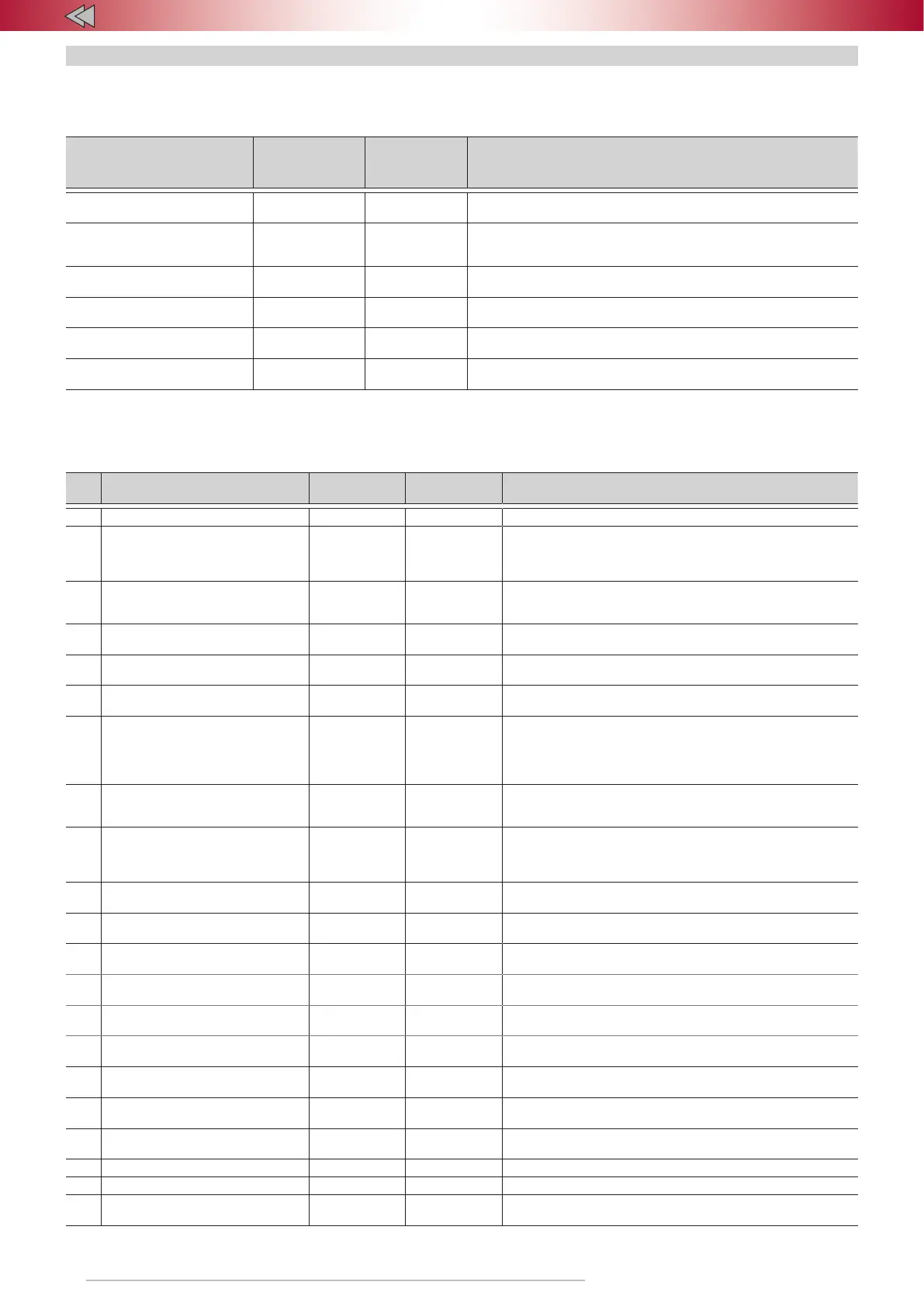
Table 6. Programming menu
Name of the menu Menu code
Number of
audio signals
Designation
Hardware features
conguration (Menu 1)
10 3 Conguration of the Alarm hardware settings
Conguration of
programmable inputs/outputs
(Menu 1.1)
11 6 Conguration of programmable inputs/outputs
User functions conguration
(Menu 2)
12 4 Conguration of the user settings
Set up shock sensors and tilt\
movement sensor
8 5
Adjustment of sensitivity of additional shock sensor; switching on/off
the tilt/displacement sensor
Remote start conguration 16 7
Menu is active only with ESM module installed or with remote start
digital output active
Heater conguration 17 8 Conguration of heater operating modes
Programming the Alarm hardware
The Alarm is programmed in accordance with "Hardware features configuration" table.
Table 7. Hardware features configuration
# Option Range
Factory default
settings
Notes
1 Vehicle model – – –
2 Engine lock 1-4 2
1 – control of a normally open relay;
2 – control of a normally closed relay;
3 – acceletator pedal lock (force to stop);
4 – starter motor lock
3 Safe lock 1-3 1
1 – Engine will be locked regardless of speed;
2 – if speed is 30km\h or lower;
3 – on complete stop
4 Type of external buttons 1-2 –
1 – analogue buttons; 2 – digital buttons.
Inputs #7 and #16 (connector Х1,18-pin)
5
Control of the factory
security system
1-2 On
1 – on
2 – off
6 Sequential door opening 1-2 Off
1 – on
2 – off
7 Hazard lights control algorithm 1-5 –
1 – pulse negative; 2 – status negative;
3 – pulse positive; 4 – status positive;
5 – lights control (negative)
8
Central lock alternative
control algorithm
1-3 –
1 – single wire pulse negative; 2 – single wire pulse negative
(if central lock state if unavaliable);
3 – two wire pulse negative
9 Siren control/Horn control 1-2 1
Selecting operating mode and polarity of output #17.
1 – Siren control. Emitting of a constant level signal (+12V).
2 – Horn control. Emitting of an intermittent negative
signal. Controls the original horn of the vehicle
10
Time interval of Timer
Channel (Comfort) feature
1-6 3 One unit equals 10 seconds.
11 External sensors multiplex mode 1-2 1
1 – multiplex operating mode of external sensors
2 – standard operating mode of external sensors
12 Engine start lock 1-2 2
1 – on
2 – off
13
Parking system control
algorithm (activation)
1-3 1
1 – by reverse gear; 2 – by speed;
3 – by reverse gear with an override
14 Parking system control button – –
It is possible to assign CAN bus recognized button,
analog button or digital button (positive/negative)
15 Speed control 1-2 1
1 – on
2 – off
16 Brake presses 1-7 3 –
17 GSM lock 1-2 2
1 – on (GSM interlock disabled)
2 – off (GSM interlock enabled)
18 Car battery warning threshold 1-15 8 (11,3) 1 – 10.6 V … 15 – 12 V
19 – – – –
20 – – – –
21 RFID tag 1-4 1
1 – not in use; 2 – RFID check when disarming; 3 – factory
remote lock; 4 – factory remote lock in high risk locations