Slave proximity
Slave top
limit switch
Drive upright
limit switch
Slave motorPower supply
FIG.2
White
Brown
Blue
Black
Black
Brown
Blue
Brown
Blue
Black
Brown
Blue
Brown
Blue
Black
Green / Yellow - Slave Motor
Green / Yellow - Power Supply
Power Supply
Slave Motor
Drive Upright
Limit Switch
Slave Top
Limit Switch
Slave
Proximity
Switch
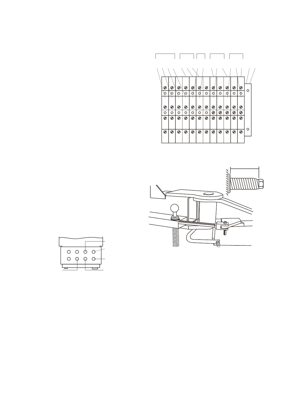
U W UV V W 9 10 11 12 13 14
L1 L2 L3 N 1 2 3 4 5 6 7 8
Earth
FIG.3
FIG.4
46 - 47 mm
10.Drill and fit eight hold-down bolts. The bolts must be
16 mm thread diameter and fitted in accordance with
the manufacturer’s instructions:
Approved expanding-type masonry anchors -
Ramset Trubolt T16125 and Hilti HSA stud anchor
M16 x 140/25.
Note: The bottom edge of the expansion sleeve on
the masonry anchor must be a minimum of 75 mm
deep in the concrete when tightened. If the base
has been shimmed up a large amount, longer
anchors will be required to ensure this depth is
reached. Tighten the anchor nut to 85NM (63 ft lbs)
If this torque cannot be reached, the connection is
not strong enough and must be redone.
Some authorities may not approve expanding type
masonry anchors. Approved adhesive masonry
anchors: Ramset Chemset capsule CHEM16 and
stud bolt M16190 and Hilti adhesive cartridge
HEAM16 x125 and anchor rod HASM16 X 190.
Tighten the anchor nut to 74 NM (55 ft lbs) after the
adhesive has cured. If this torque cannot be
reached, the connection is not strong enough and
must be redone.
Note: These fasteners require a minimum
concrete thickness and hole depth of 125 mm.
11.Add shims under the base frame, at the back of the
columns, as per Fig. 1, until there is only a small
gap. Measure the size of the gap with feeler
gauges. Loosen the 8 hold-down bolts. At the back
of the column, add extra shims to fill up the
measured gap and raise the height an extra 1.4 to
2.0mm. Eg for 0.6mm gap, add between 2.0 and
2.6mm of shims. Retighten and retorque all the
hold-down bolts.
12.Feed the wiring from the slave column through the
overhead crossbeam and uprights and into the
control box on the drive column as per Fig. 2.
Tighten the cable glands to seal the control box.
Connect the wiring to the numbered terminal strip in
the control box as per Fig. 3.
13.Apply a smear of grease in the lifting arm pivot holes
and the carriage pivot holes. Fit the lifting arms to
the carriages. Fit the pivot pins and retain with a
circlip top and bottom as per Fig. 4. Check the
circlips are fully in their grooves.
14.Fit the footguards to the lifting arms as per Fig.4
and tighten the bolts until the spring is compressed
to 46 to 47mm long.
15.Fit the tool trays to 2 of the lifting arms with the
M6 x 16mm long screws and the 19mm diameter
x 2mm thick flat washers. Tighten the screws up
snug tight only (do not over tighten as this will
distort the tray). Check all the arms slide in and
out freely.
16.Place a lifting pad in the hexagonal hole in each
lifting arm.
17.Fit the armlock devices to the carriages and arms
as per Fig. 4. Check that the circlips are fully in
their grooves and the Nyloc nut is tightened up
fully on the M8 x 55mm long cap screw. Lift up
on each black knob and check each arm moves
freely through the full arc. Release the knob and
check the arm is locked.
Page 5
(Neutral)
 Loading...