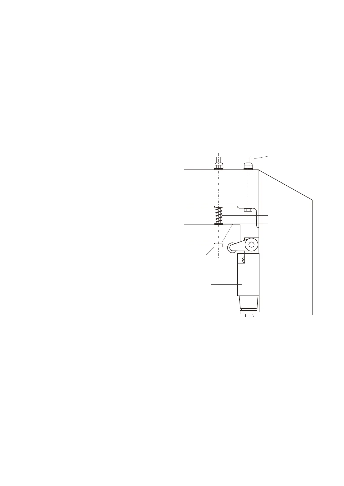
FIG.5
M6 x 65L Bolt
M6 Nyloc Nut
Cross Beam
25mm
Gap
M6 x 120L Bolt
Upright
V18944 Spring
Rubber
Washer
4 off
Limit Switch
18. Connect the power supply from the mains isolator
switch (adjacent to the hoist), to the control box on
the drive column. Use 4-core plus earth, 7 strand,
2
2.5mm copper cable. Fit the cable through the
cable gland as shown in Fig. 2 and tighten the gland
to seal the control box. Connect the wires as per
Fig. 3.
Note: This must be done by a qualified electrician.
19. Switch on the power to the hoist. Turn the isolating
switch to the vertical “on” position and wait until the
warning light comes on. Press the up button. The
hoist should go up. If it goes down, stop
immediately and turn off the mains isolator. Swap
two of the power supply wires at the terminal strip in
the control box. Switch the power back on. Check
the hoist goes up when the up button is pressed.
20. Drive the hoist fully up to check operation of the top
limit switches. Drive the hoist fully down to check
the operation of the bottom limit switches. Swing
the four lifting arms in and out with the lifting pads
screwed fully down. If the arms hit the floor in any
position, adjust the arms on the bottom limit
switches so the lifting arms clear.
Manually wind the hoist up by rotating the screw
pulley to check the carriage is still supported by the
lifting nut, not sitting on the bottom of the column.
Adjust the bottom limit switches so the lifting nuts
are still carrying the carriage when the hoist is
driven down fully.
21. Fit the covers over the bottom limit switches using
the M6 x 10 mm long socket head cap screws. Fit
the motor covers over the vee belts and secure with
the M4 x 10 mm long screws and large flat washers.
Fit the black plastic caps over the M12 nuts on the
back of each column.
22. Climb up a ladder and adjust the overhead collision
trip bar limit switch so that it just clicks on when the
trip bar is lifted then lowered slowly. For coarse
adjustment move the switch arm on its splined
shaft. For fine adjustment move the whole switch
up or down. Test the operation of the trip bar by
lifting up the trip bar at mid-span while driving the
hoist up. The hoist must stop! Release the trip bar.
The hoist must drive up.
23. Drive the hoist up 1 m clear of the floor. Fit a funnel
through the hole in the front blind in the drive
column. Pour in half a litre of the recommended
extreme pressure oil (supplied). Pour the other
half into the slave column.
Note: 1/2 litre of oil will half-fill the oil reservoir in
each column. Do not have the reservoirs more than
half full as the excess oil will be quickly lost.
24. Drive the hoist up and down four or five times to
lubricate the lifting screws.
25. Fit the heaviest available vehicle (maximum 3
tonnes) on the hoist and drive the hoist up and
down two or three times to test the operation of the
top and bottom limit switches and that it runs
smoothly and quietly. Stop at mid-height and check
it drives up again.
26. Demonstrate how the hoist operates to the owners
and operators. Give them this instruction manual
and ask them to read it and keep it for future
reference.
Page 6
 Loading...