Figure 2-3
7. Move the exhaust push tube to one side; rotate the
exhaust rocker lever to permit removal of Cummins
crosshead.
8. Install the new TecBrake crosshead. Note that it
comes with a new crosshead adjusting screw and nut.
Lubricate the crosshead and guide with oil before
installation. Make sure the crosshead adjusting screw is
on the exhaust manifold side of the engine.
9. Adjust the crosshead by holding it down against the
valve stem nearest the push tube, then turn in the
adjusting screw until it touches the valve stem.
10. Hold the adjusting screw in place and tighten the
locknut to 25 lbft (35N*m). Repeat operation for all
crossheads
6. Remove the rocker arm adjusting screws from the
exhaust rocker levers. Retain the Cummins locknuts and
screws.
Figure 2-4
11. Remove the injector adjusting screws from injector
rocker arm. Install the TecBrake injector adjusting screws
(hex head) furnished in kit. Reuse the Cummins
adjusting screw lock nuts.
CAUTION
The injector adjusting screw used in the TecBrake
Model T430A has a 5/8" hex head and height of 2".
Earlier model engine brakes used either a 5/8" or 7/
16" hex head and were 2.2" in height. These screws
are not interchangeable. Use of the wrong screw will
result in damage to the engine and brake.
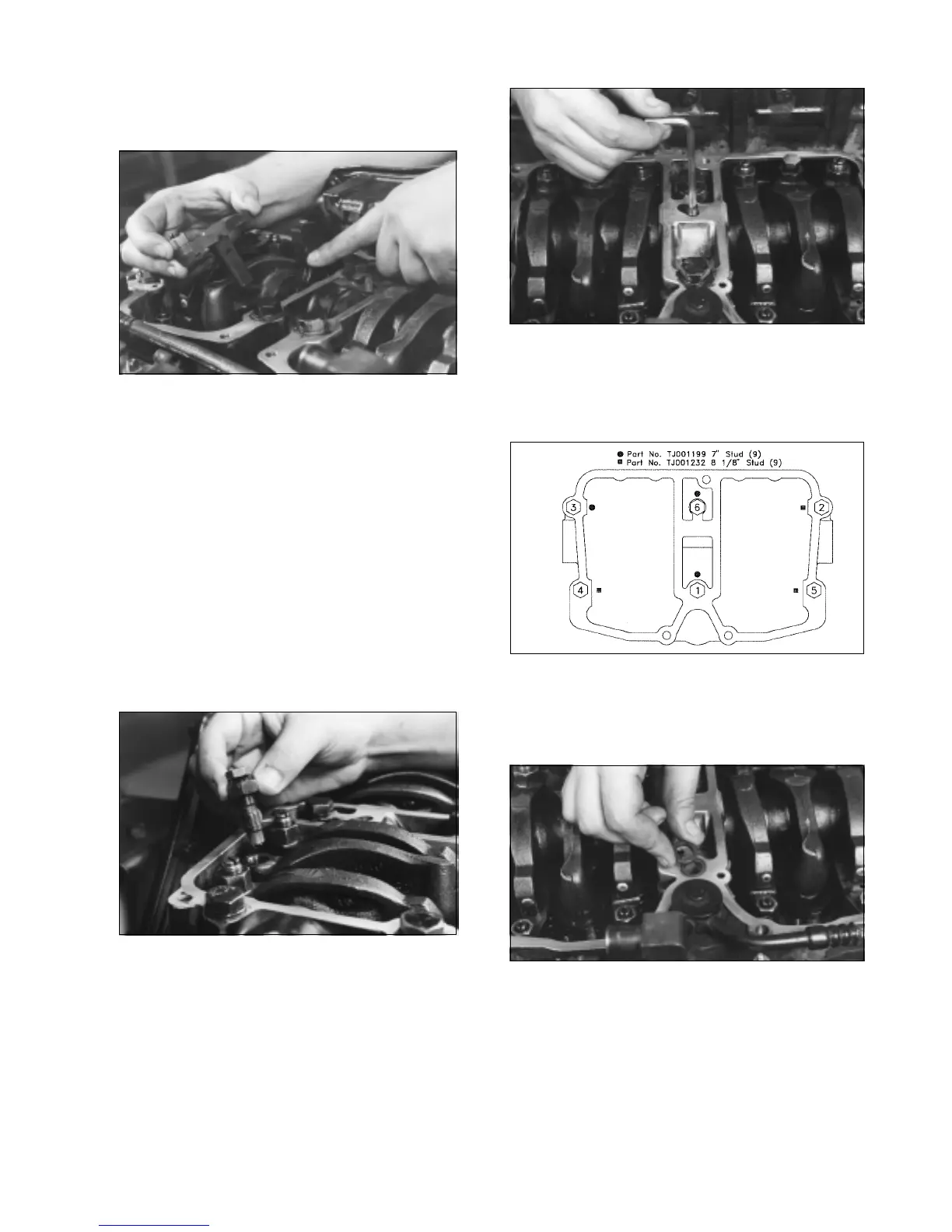
Figure 2-5
12. Remove the Cummins solid rocker shaft locking screws
from the cylinder heads and replace them with the hollow
set screws supplied in kit. Be sure screw is below flat surface
of the rocker housing when installed.
Figure 2-6
13.Remove three capscrews from each rocker housing in
positions1, 2, and 3 as indicated in Figure 2-6.
Do not
remove all six of the capscrews at the same time, as
this will permit the housing and gasket to move.
Figure 2-7
14. Install the special bearing washer into each rocker
housing capscrew bolt hole with the smaller diameter down.
NOTE: Bearing washers are not required in positions 2
and 5 if a fan brace is used.
15. Install studs supplied with kit in positions1, 2 & 3 as
indicated in Figure 2-6. Torque studs to 70 lbft (95 N*m).
16. Remove capscrews from positions 4, 5 & 6 as indicated
in Figure 2-6. Install new studs and torque to 70 lbft).
2
 Loading...