Figure 4-7
2. Bleed air from the engine brake housing. Accelerate
the engine to about 1800 RPM then release the throttle.
Quickly depress the solenoid as shown to cause the
brake to operate. This process should be repeated 5-6
times on each brake assembly in order to fill the housings
with lube oil. When all of the air has been removed the
brake should operate immediately when the solenoid is
depressed.
SECTION 5- ELECTRICAL SYSTEM INSTALLATION
Installation of the electrical system involves the mounting
of dash switches, a clutch switch, and a fuel pump switch.
An optional foot switch may be installed in place of the
clutch switch. Wiring harnesses are provided in the kit to
complete the installation. Refer to the wiring diagram Figure
5-8.
Dash Switches
Dash switches should be installed in dash where they are
visible and convenient to operate.
1. Drill holes in dash to accommodate switches and install
switches with proper name plates.
Clutch Switch
It is recommended that the clutch switch be mounted inside
the vehicle cab to protect it from road contamination.
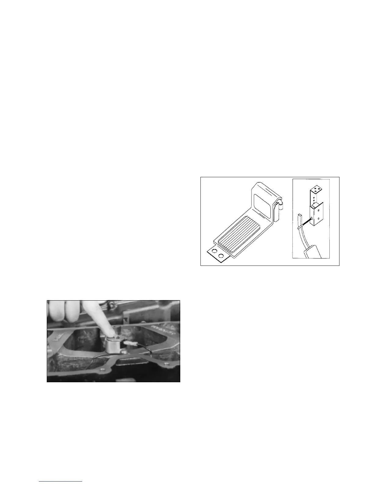
Figure 5-1
1. Mount the clutch switch in a convenient location near
the clutch pedal so that movement of the clutch pedal will
contact the clutch switch actuator arm. See Figure 5-1.
2. Adjust the clutch switch so that the actuator arm is
deflected from 1" to 1.5" (25 mm to 38 mm) when the clutch
is in the up (clutch engaged) position.
3. Check the switch by depressing the clutch. The switch
should "click" to an open electrical position as soon as the
free play in the clutch is taken up. When the clutch is
released, the switch should "click" to a closed electrical
position.
Optional Foot Switch
An optional foot switch may be used in place of the clutch
switch. The foot switch should be mounted on the cab floor
to the left of the clutch pedal and should be located so that
it can be conveniently operated with the drivers left foot.
Slave Piston Adjustment
Adjustment of the slave piston adjusting screw is critical.
Proper adjustment is necessary in order to provide peak
braking efficiency without over stressing the engine.
Slave piston adjusting screw adjustment must be
made with the engine stopped and engine
temperature stabilized below 140 ºF
.
1. Set engine brake valve lash using the adjusting
screw located above each slave piston. The engine
crankshaft must be rotated to allow the exhaust valve to
be fully closed prior to making adjustment on each
cylinder.
2. Back out the adjusting screw on each cylinder to be
adjusted. Using a 0.018" feeler gauge between the slave
piston and the exhaust crosshead, turn in the slave piston
adjusting screw until a slight drag is felt on the gauge.
3. Tighten the adjusting screw lock nut to 25 lbft (35
N*m) torque. Rotate the crankshaft, adjusting each
adjusting screw in firing order sequence.
Operational Check
Installation of the brake housings is now complete.
Functioning of the brakes should be checked before
proceeding further.
1. Start the engine and let it idle for a short time.
CAUTION
Wear eye protection. When engine is running with
valve covers removed, oil splashing will occur. Take
precautions to prevent oil contaminating engine and
engine compartment.
5
 Loading...