INSTALLATION MANUAL
TECBRAKE MODEL T430A ENGINE BRAKE
FOR CUMMINS NTC/88NT SERIES ENGINE
SECTION 1- INTRODUCTION
The TecBrake T430A engine brake may be installed on
popular versions of the Cummins NTC/88NT series
engine. It can not be installed on earlier versions of the
Cummins NTC series engines, which use a different
cylinder head configuration. The TecBrake application
chart can be used to identify the engine model and
determine if the engine is approved for installation of an
engine brake.
The Model T430A engine brake will fit on NTC/88NT
engines equipped with either Fixed Timing or Step Timing
Control (STC). Earlier STC engine applications required
that the rear brake housing be connected to the Step
Timing Control Valve. This is not required on the TecBrake
Model T430A.
NOTICE
The TecBrake Engine Brake is designed as a device
for slowing a vehicle, not stopping it. It is to be used
in conjunction with, but not a substitute for the
vehicle’s service brakes. The service brakes must
be in good operating condition and used to bring
the vehicle to a complete stop.
Material Required
The TecBrake kit includes all of the parts required to
make an installation on the most common engine
configurations.
Prior to making installation, determine the engine CPL
number to verify that the engine brake being installed is
correct for the engine. The CPL number can be found on
the engine identification plate that is located on the
engine gear case flange.
Special Tools
The following special tools are required for installation:
1. Crowfoot wrench- 9/16"
2. Crowfoot wrench- 5/8"
3. Socket, extra deep- 5/8"
4. Feeler gauge- 0.018"
5. STC Tappet setting tool- Cummins Part No.3822648
Recommended Torque Values
Crosshead Adj. Screw locknuts - 25 lbft (35 N*m)
Engine Brake Hold-down Nuts - 60 lbft (80 N*m)
Rocker Housing Studs- 70 lbft (95 N*m)
Rocker Arm Adj. Screw Nuts - 45 lbft (60 N*m)
Slave Piston Adj. Screw Nuts - 25 lbft (35 N*m)
Fuel Pump Sw. Mtg. Brkt. Bolts- 100lbin (10 N*m)
SECTION 2 - ENGINE PREPARATION
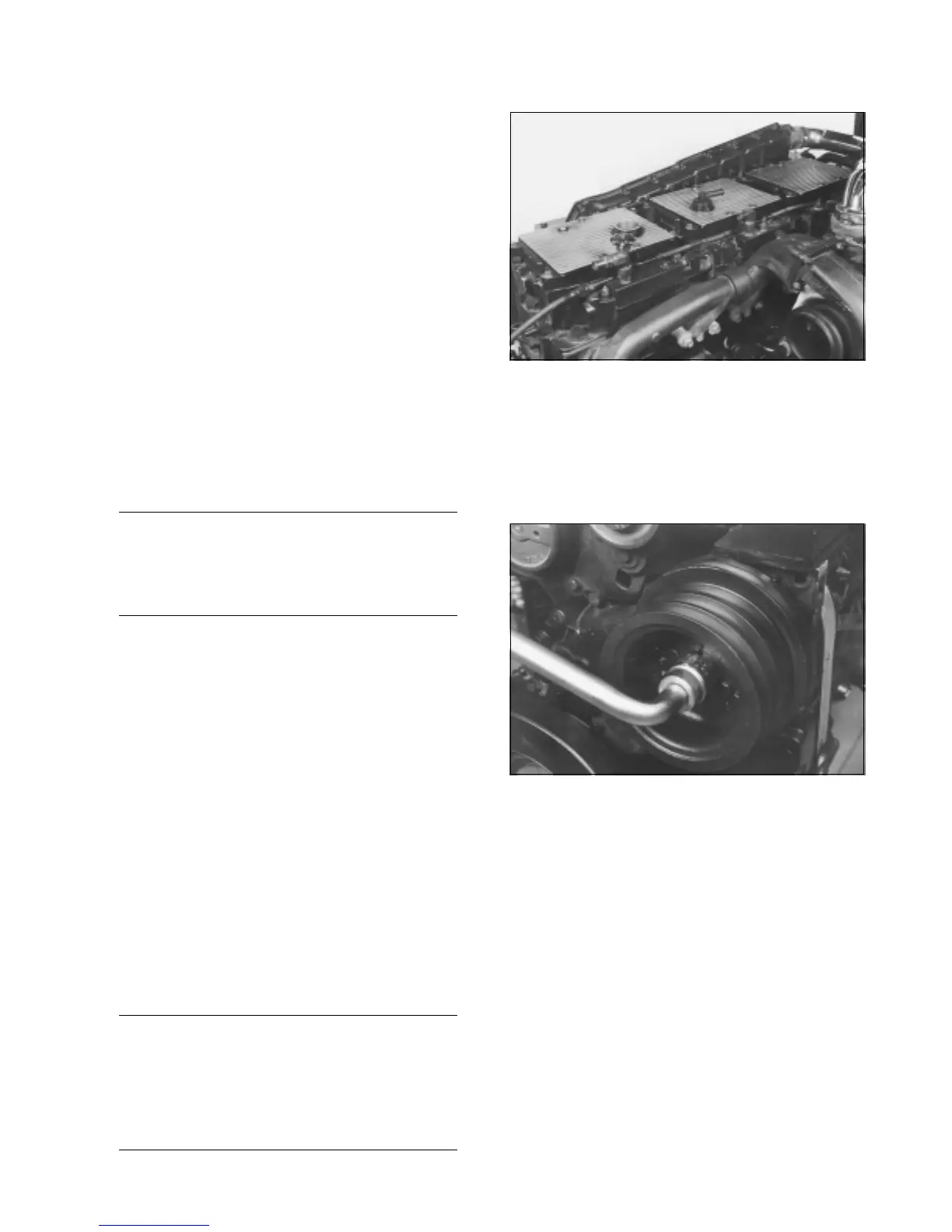
Figure 2-1
1. Thoroughly clean engine before beginning
installation. Remove all engine components necessary to
permit access to cylinder heads. Remove valve covers.
It is not necessary to remove the rocker lever housing
to install the Model T430A engine brake.
Figure 2-2
2. Rotate engine crankshaft to proper position for making
adjustments to Injector, exhaust valve, and slave pistons
later on.
3. Turn crankshaft clockwise until the "A" mark on the
accessory drive pulley is aligned with pointer on the gear
case cover.
4 At this point, the intake and exhaust valves should be
closed for cylinder No. 5 and the rocker levers should be
"loose". The injector plunger for cylinder No. 3 must also
be at the top of it’s travel. If it is not, turn the crankshaft
another 360 degrees and realign the "A" mark with the
pointer.
5. After the engine brake is installed the engine will be in
position to begin setting the injector, exhaust valve and
slave piston adjusting screws.
1
 Loading...